power supply circuit
Power Supply Monitor for TTL
Published:2013/10/29 21:03:00 Author:lynne | Keyword: Power Supply Monitor | From:SeekIC


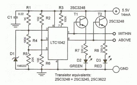
This simple TTL power supply monitor circuit monitors the 5-volt level TTL power line and gives a signal whether the supply voltage is outside or within the necessary range or “window”. The heart of thepower supply monitoris a low-current integrated window comparator. The center of this window is set at 2.5 volt +/- 0.005 volt by the bandgap reference diode D1 which is connected to pin 2 of LTC1042. The width of this window must be 20% (+/- 10%) of the reference voltage.The reference voltage is reduced by 25% through R4 and R5 and fed to pin 5 of the IC. The monitored voltage is then fed to pin 2 so that the green LED D2 will light up when the voltage is within the desired range. Otherwise, the red LED D3 will light up signalling that the voltage is out of range.
TTL power supply monitor circuit diagram
Reprinted Url Of This Article:
http://www.seekic.com/circuit_diagram/Power_Supply_Circuit/Power_Supply_Monitor_for_TTL.html
Print this Page | Comments | Reading(3)

Article Categories
power supply circuit
Amplifier Circuit
Basic Circuit
LED and Light Circuit
Sensor Circuit
Signal Processing
Electrical Equipment Circuit
Control Circuit
Remote Control Circuit
A/D-D/A Converter Circuit
Audio Circuit
Measuring and Test Circuit
Communication Circuit
Computer-Related Circuit
555 Circuit
Automotive Circuit
Repairing Circuit
Code: