© 2008-2012 SeekIC.com Corp.All Rights Reserved.
power supply circuit
Simple Micro Ampere Meter Circuit
Published:2013/12/1 20:25:00 Author:lynne | Keyword: Simple Micro Ampere Meter Circuit | From:SeekIC

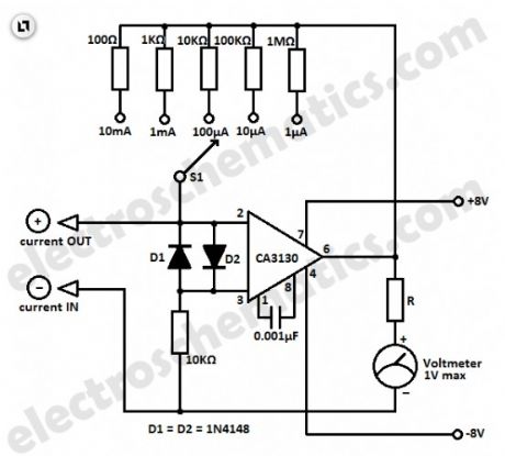
This simple micro ampere meter circuit can help in measuring small currents in five ranges: from 1 µA to 10 mA. The meter is working in this way: the current being measured Ix shifts the input voltage resulting to an output voltage with an inverted polarity.
The output voltage of the opamp CA3130 is proportional to the measured current Ix.By selecting the proper feedback resistors through S1, the output voltage by full meter deflection is 1 volt in all measuring ranges.
The value of the series resistor R must be selected for the particular meter being used. For example if a 1 mA meter is used, the total resistance (the sum of the resistor R and the coil resistance Ri of the meter) must be 1kΩ. If a 100 µA meter is used, the total resistance must be 100 kΩ. If needed, a potentiometer can be used for the R.
Micro ampere measurement circuit schematic
Reprinted Url Of This Article:
http://www.seekic.com/circuit_diagram/Power_Supply_Circuit/Simple_Micro_Ampere_Meter_Circuit.html
Print this Page | Comments | Reading(3)

Article Categories
power supply circuit
Amplifier Circuit
Basic Circuit
LED and Light Circuit
Sensor Circuit
Signal Processing
Electrical Equipment Circuit
Control Circuit
Remote Control Circuit
A/D-D/A Converter Circuit
Audio Circuit
Measuring and Test Circuit
Communication Circuit
Computer-Related Circuit
555 Circuit
Automotive Circuit
Repairing Circuit
New published articles
Response in 12 hours

Code: