LED and Light Circuit
Index 60
FLUORESCENT_TUBE_DISPLAY_DRIVER
Published:2009/6/15 23:50:00 Author:May

A fluorescent tube or display can be driven with a 4543B IC, as shown. (View)
View full Circuit Diagram | Comments | Reading(792)
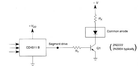
4511B_COMMON_ANODE_DISPLAY_DRIVER
Published:2009/6/15 23:49:00 Author:May

The use of a switching transistor (like a 2N2222 or 2N3904) allows use of the CD4511B with a common-anode display. Ry should be chosen to provide about 1 mA to drive Q1 and Rx should provide enough current to drive the display. For this circuit, the transistor gain (HFE) should be at least the ratio of the segment drive current to the current through Rx (View)
View full Circuit Diagram | Comments | Reading(1081)
GAS_DISCHARGE_TUBE_OR_DISPLAY_DRIVER
Published:2009/6/15 23:47:00 Author:May

To drive the display, RA should provide a drive of about 1 mA to the gas discharge tube. RB is a current-limiting resistor. (View)
View full Circuit Diagram | Comments | Reading(725)
4543B_7_SEGMENT_LCD_DRIVER
Published:2009/6/15 23:42:00 Author:May


The circuit shows a frequently-used method of driving an LCD display. A square-wave drive is necessary for this application. (View)
View full Circuit Diagram | Comments | Reading(1599)
7_SEGMENTLEDDISPLAY_DRIVER
Published:2009/6/15 23:41:00 Author:May

AIL IC1 like a 7447 drives a 7-segment commoll anode LED display.Current limiting reslstor R should limit the segment current to the rated value at maxlmum supply voltage A sample calculation is shown (View)
View full Circuit Diagram | Comments | Reading(3401)
7_SEGMENT_COMMON_CATHODE_LED_DISPLAY_DRIVER
Published:2009/6/15 23:40:00 Author:May

A CD4511B CMOS LED display driver can be used to drive a common cathode LED display. Cur-rent limiting resistors limit the segment current to the rated value at maximum supply voltage. A sample calculation is shown. (View)
View full Circuit Diagram | Comments | Reading(1444)
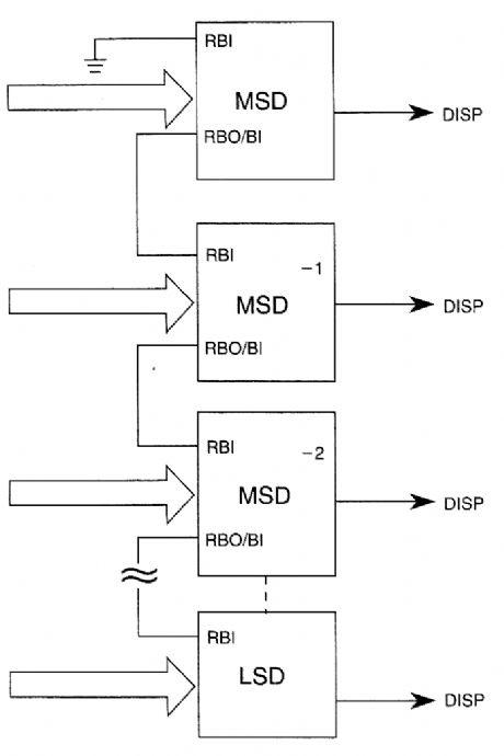
LED_DISPLAY_LEADING_ZERO_SUPPRESSOR
Published:2009/6/15 23:33:00 Author:May

The diagram shows how to connect 7447-type IC devices for leading-zero suppression in an LED display. (View)
View full Circuit Diagram | Comments | Reading(724)
7_SEGMENT_LCD_DRIVER
Published:2009/6/15 23:32:00 Author:May

This circuit shows how a 7448 IC is used to drive a 7-segment LCD display. Atn external 50-Hz square wave supplies necessary phase signals to the back plane of the display. (View)
View full Circuit Diagram | Comments | Reading(3684)
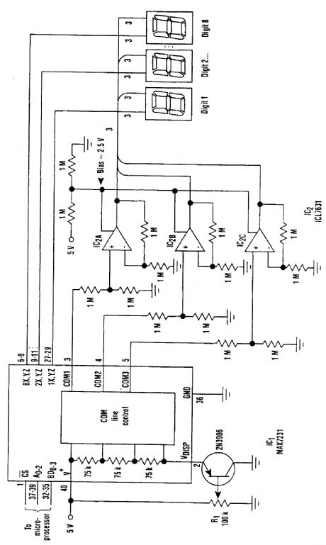
LARGE_LCD_DISPLAY_BUFFERING_DRIVER
Published:2009/6/15 23:30:00 Author:May

Large LCD devices of 1 or more exhibit a large driving capacitance to the driver circuits. To solve this problem, the drive cir-cuit shown (see the figure) introduces a buffer amplifier for each of the three common lines. Each amplifier can be programmed independently for a quiescent current of 10, 100, or 1000μA. In this application, the bias network applies a voltage that sets the three quiescent currents to 100μA.The display driver and triple op amp operate between 5 V and ground, and the COM signals range from 5 V to ≈1 V. To en-sure that these signals remain within the amplifiers' common-mode range, the signals are attenuated by one-half and the buffers operate at a gain of two. The circuit drives eight 1-inch displays, and is suitable for ambient temperature variations of 15°F or Iess.At the highest expected temperature, R1 should be adjusted so that no off segments are visible. (View)
View full Circuit Diagram | Comments | Reading(816)
CASCADED_4026B_COUNTER_DISPLAY_DRIVER_CIRCUIT
Published:2009/6/15 23:21:00 Author:May

CASCADED 4026B COUNTER/DISPLAY DRIVER CIRCUIT (View)
View full Circuit Diagram | Comments | Reading(2399)
4033_DISPLAY_CIRCUITRY_COMMON_CATHODE
Published:2009/6/15 23:15:00 Author:May

TO drive two or more common-cathode displays two or more 4033 decode counters can be cascaded (View)
View full Circuit Diagram | Comments | Reading(782)
Five flash lamp string circuit (4)
Published:2011/7/5 21:54:00 Author:zj | Keyword: Five flash, lamp string circuit

In the graph, SSR1 to SSR5 use TAC081 IC type solid state relay. T uses 220V / 6V, 5VA small quality requirements of power transformers. Itrequires power fora long time without heating. (View)
View full Circuit Diagram | Comments | Reading(731)
Five flash lamp string circuit(2)(M1512P)
Published:2011/7/5 22:00:00 Author:zj | Keyword: Five flash, lamp string circuit
View full Circuit Diagram | Comments | Reading(562)
The time-base circuit AC light regulating lamp circuit
Published:2011/7/5 22:15:00 Author:zj | Keyword: The time-base circuit, AC light regulating lamp circuit
View full Circuit Diagram | Comments | Reading(689)
Ten flash lamp string circuit
Published:2011/7/5 22:22:00 Author:zj | Keyword: Ten flash, lamp string circuit

As shown in the figure itis composed of a digital integrated circuit CD4017 consisting of ten flash lamp string controller. VT1 ~ VT10use MCR100-8 type small outline of a unidirectional thyristor. (View)
View full Circuit Diagram | Comments | Reading(1267)
SS0622 Touching stepping dimmer circuit
Published:2011/7/24 22:46:00 Author:Ecco | Keyword: Touching stepping dimmer

Touching stepping dimmer composed of the SS0622 IC is shown as the chart, and it canprovidetwo ways of four-gear stepping touching dimmeraccording to the needs of the users.
(View)
View full Circuit Diagram | Comments | Reading(1068)
Crossed flash circuit
Published:2011/7/16 3:39:00 Author:leo | Keyword: Crossed flash

In order to get different colors, we divideLEDs into two lines horizontally and two lines vertically. And we use two kinds of colors of LED to make it come true. LM324(IC1) is the center of saw tooth oscillator circuit while IC2 and IC3 are the center of comparator, whose referring voltage is gotten through resistance series R13 to R20.And VR1 is used to adjust the referring voltage value of comparator A4 to A10. (View)
View full Circuit Diagram | Comments | Reading(638)
Southeast Ling Sheng Room Lamp and baggage compartment lamp electric system circuit
Published:2011/7/20 20:37:00 Author:leo | Keyword: Room Lamp, baggage compartment lamp
View full Circuit Diagram | Comments | Reading(549)
Southeast Ling Sheng tail lamp,position lamp and license lamp electric system circuit
Published:2011/7/20 20:32:00 Author:leo | Keyword: Tail lamp, position lamp, license lamp
View full Circuit Diagram | Comments | Reading(756)
Southeast Ling Sheng glove box lamp electric system circuit
Published:2011/7/20 21:10:00 Author:leo | Keyword: Glove box lamp, electric system
View full Circuit Diagram | Comments | Reading(618)
| Pages:60/72 At 204142434445464748495051525354555657585960Under 20 |
Circuit Categories
power supply circuit
Amplifier Circuit
Basic Circuit
LED and Light Circuit
Sensor Circuit
Signal Processing
Electrical Equipment Circuit
Control Circuit
Remote Control Circuit
A/D-D/A Converter Circuit
Audio Circuit
Measuring and Test Circuit
Communication Circuit
Computer-Related Circuit
555 Circuit
Automotive Circuit
Repairing Circuit


