
Control Circuit
Index 199
Outdoor Lighting Automatic Control Principle Circuit
Published:2011/7/18 9:35:00 Author:Robert | Keyword: Outdoor, Lighting, Automatic, Control, Principle

The picture shows the outdoor lighting automatic control principle circuit. (View)
View full Circuit Diagram | Comments | Reading(927)
The phase detection circuit composed of MAX4521
Published:2011/7/15 22:18:00 Author:Borg | Keyword: phase detection circuit

This is a phase detection circuit composed of computing amplifier TLC072 and analog switch MAX4521, which is fitted in PLL circuits or lock amplifiers. The voltage of the power supply is ±5V, the LEV of input and output signals is under ±4V, the working frequency is 10HZ~1OOkHZ. Ui1 and Ui2 are the input sine wave and square wave respectively, the duty cycle of the square wave is 50%, the output waveform of A1 is U. see as figure 7-15(b), when Ui1 and Ui2 are in the same phase, the output of A1 is shown as the waveform of ① in figure (b); when Ui1 and Ui2 are in the phases that differ 90°, the output of A1 is shown as the waveform of ② in figure (b). (View)
View full Circuit Diagram | Comments | Reading(1951)
The pulse width modulation circuit composed of 74HCUO4
Published:2011/7/17 20:46:00 Author:Borg | Keyword: pulse width, modulation circuit

In the figure is the pulse width modulation circuit composed of 74HCUO4. this is a multi-resonance oscillator composed of the Miller integrating circuit and time lag comparing circuit, if the rectangular wave duty cycle is changed by the input low frequency signal of R1, the pulse width can be modulated. C1 is the AC separation capacitor. The frequency of the rectangular wave is (1/4)[1/(R2C2)](R4/R3). According to the given element parameter, the frequency is about 900KHZ. R2 can compose a backward feedback, which is used to reduce the distortion. As the threshold voltage and output voltage amplitude are relevant to the power supply voltage, so S/N is affected by the power supply noise, which is to be noticed.
(View)
View full Circuit Diagram | Comments | Reading(586)
The synchronous wave detection circuit composed of analog switch
Published:2011/7/15 22:05:00 Author:Borg | Keyword: wave detection circuit, analog switch

This is the synchronous wave detection circuit composed of analog switch. As the circuit is installed with an analog switch, so it can work as the wave detection circuit of the low frequency lock phase amplifier under thousands of HZ of frequency. The analog switch AD7515 shifts the basic input signal quickly, when the switch state is shown in the figure, the non-inverting input terminal of A1 is connected with the earth, the input signal is reversed; when the switch is connected with the lower terminal, the inverting phase input terminal of A1 is connected with the earth, as R1 and R2 distribute the voltage, so that A1 is turned into the amplifier which magnifying time is once.
(View)
View full Circuit Diagram | Comments | Reading(734)
The synchronous wave detection circuit of polarity switch
Published:2011/7/15 21:41:00 Author:Borg | Keyword: synchronous, wave detection circuit

This is the synchronous wave detection circuit of polarity switch. In the circuit, the impedance switch and buffer circuit can be formed by A1; A2 forms the phase inverting and non-inverting amplifier circuit; when VT2 is conducting, the non-inverting phase of A2is connected with the ground and becomes a -1 amplifier circuit; when VT2 is blocked, the input signal is added to the non-inverting input terminal of A2, as the impedance of A2 is very high, so the inverting and non-inverting terminal have the same LEV, and the inverting terminal is moving with it, therefore, VT2 works as the follower whose magnifying time is once.
(View)
View full Circuit Diagram | Comments | Reading(699)
The synchronous wave detection circuit of full method
Published:2011/7/17 21:02:00 Author:Borg | Keyword: synchronous, wave detection circuit
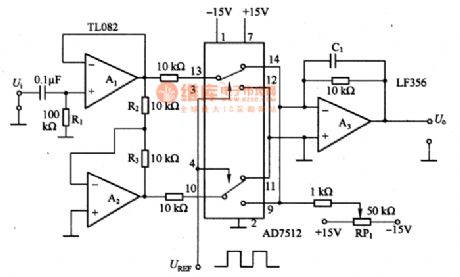
In the figure is the synchronous wave detection circuit of full method. In the circuit, A1 and A2 can compose the balance output circuit of forward/backward phase output, even when the R2/R3 ratio is 1. the analog switch AD7512 plays an important role, the figured connector position is the inverting input terminal of the forward output(A1 output is the forward hemi-cycle of the input signal) linking to A3; if the connector is lower, the inverting output (A2 output is the backward hemi-cycle) is conducting. Considering the period of an input signal in the way, A3 output terminal can get a full-wave output.
(View)
View full Circuit Diagram | Comments | Reading(839)
The tune circuit composed of MOSFET and inductance coils
Published:2011/7/17 20:24:00 Author:Borg | Keyword: tune circuit, inductance coils
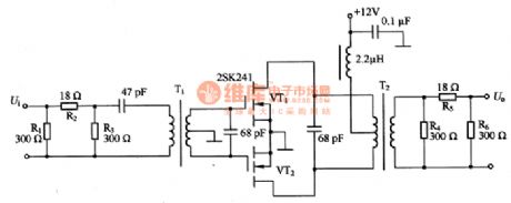
This is the tune circuit composed of MOSFET and inductance coils, which can only amplify the signals of certain frequency, it is fitted in the terminal circuit of low power emitters. The circuit is in push-pull pattern, so there few odd harmonic waves, its gain without connecting with attenuator is +20~+30dB at the frequency of 14MHZ. in the circuit, R1, R2 and R3 composed the input attenuator, R4, R5 and R6 form the output attenuator; VT1 and VT2 are the 2SK241 power MOSFET. If larger gain and output power are needed, one more parallel 2SK241 can meet the need. When the gain is two large and the impedance may be mismatching, an attenuator can be fixed in it.
(View)
View full Circuit Diagram | Comments | Reading(568)
The phase wave detection composed of 74HC4053
Published:2011/7/17 20:36:00 Author:Borg | Keyword: phase wave, detection circuit
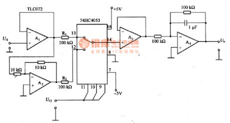
This is the phase wave detection circuit composed of 74HC4053. the circuit consists of the computing amplifier TLC072 and the analog switch 74HC4053, but the conducting resistance of the analog switch changes with the temperature and the power supply voltage. In the circuit, the output of the analog switch 74HC4053 is connected with the voltage follower composed of A3, so the conducting resistance doesn’t affect the output. If the impedance of the input signal is very low, then A1 is needless. Although the 74HC analog switch can’t be assure of “breading first, connecting second”, if 74HC4053 makes both A1 and A2 short, it won’t problematic.
(View)
View full Circuit Diagram | Comments | Reading(2820)
Protection Circuit of Transistor Regulating Power Supply
Published:2011/7/17 7:16:00 Author:Michel | Keyword: Regulating Power Supply, Protection Circuit

a、b、c、d、e are protection circuits of transistor regulating power supply.The voltage stabilizer load protection circuit has current limiting type and current cut-off type. In the picture,(a)~(d) are current limiting protection circuit.In the picture 1,VT1 base of electricity flows through VT1 VD1 and VD2 circulation when the voltage drop is more than VD1 Rs and VD2 positive voltage.Therefore, its emitter current is restricted and it uses the sharp increasing characteristics of diode forward voltage current.In figure (b) and (c),transistor UEB which has the same characteristics as diode,the VT3 UBE is controlled by testing voltage drop on RS to limit the VT1 emitter current and the limited current I. = 0.6 V/Rs.
(View)
View full Circuit Diagram | Comments | Reading(731)
μPC1094 control circuit, main features and pin of DC-DC circuit and power supply monitor
Published:2011/7/11 6:21:00 Author:Lucas | Keyword: control circuit, main features , pin , DC-DC circuit , power supply monitor

μPC1094 switching regulator control circuit
The standby current is 1.6mA; the output stage is the totem pole circuit, and the maximum output capacity is 1.2A; it can directly control the power MOS FET; the maximum supply voltage is 26V; the maximum output voltage is 26V; the maximum DC output is 100mA.
(View)
View full Circuit Diagram | Comments | Reading(1139)
μA78S40 control circuit, main features and pin of DC-DC circuit and power supply monitor
Published:2011/7/11 6:13:00 Author:Lucas | Keyword: control circuit, main features , pin , DC-DC circuit , power supply monitor


μA78S40 switching regulator control circuit
It is composed of 1.3V reference voltage, oscillator, current limit circuit, error amplifier, switching transistor, switching diode and operational amplifier; it may constitute boost, buck and switching regulator; supply voltage range is 2.5 ~ 40V; output voltage range is 1.3 ~ 40V; the maximum power diode reverse voltage is 40V; maximum reference current is 10mA; the maximum current flowing power diode and transistoris 1.5A; plastic power is 1.5W, ceramic sealing is 1.0W; μA78S40M operating temperature is -55 ~ +125 ℃, μA78S40C is 0 ~ +70 ℃.
(View)
View full Circuit Diagram | Comments | Reading(647)
W494 control circuit, main features and pin of DC-DC circuit and power supply monitor
Published:2011/7/11 6:26:00 Author:Lucas | Keyword: control circuit , main features , pin , DC-DC circuit , power supply monitor

W494 switching regulator control circuit
It is the switching regulator control circuit with fixed frequency; frequency range is 1 ~ 300kHz; output voltage is 40V; output current is 200mA; output level can select single-end or push-pull way; it is equipped 5V ± 5% reference voltage with adjustable resting time; the maximum input voltage is 42V; oscillator can be externally synchronized. Swapping types: TL494, μA494.
(View)
View full Circuit Diagram | Comments | Reading(530)
W1525A control circuit, main features and pin of DC-DC circuit and power supply monitor
Published:2011/7/11 6:02:00 Author:Lucas | Keyword: control circuit , main features , pin , DC-DC circuit , power supply monitor

W1525A/2525A/3525A switching regulatorcontrol circuit
Operating supply voltage range is 8 ~ 35V; it has 5.1V reference voltage; error is ± 1%; oscillator frequency range is 100Hz ~ 500kHz; it has adjustable stationary time and internal soft-start and hysteretic input voltage lockout; it contains dual totem pole output drivers; the maximum supply voltage is 40V; the maximum collector voltage is 40V; the maximum charge current of oscillator is 5mA; the maximum output current is 500mA; the maximum reference output current is 50mA; when ambient temperature is 70 ℃, the power consumption is 1000mW; W1525A operating temperature is -55 ~ +125 ℃, and W2525A is -25 ~ +85 ℃, and W3525A is 0 ~ +70 ℃.
(View)
View full Circuit Diagram | Comments | Reading(579)
HJ94015 Christmas tree music lights control circuit
Published:2011/7/18 5:53:00 Author:Lucas | Keyword: Christmas tree , music lights , control circuit

The circuit is shown as the chart. It is composed of the integrated circuit HJ94015 with simple circuit, good audio and video effect. HJ94015 is integrated circuit which is designed specifically for the Christmas tree with DIP-16 plastic structure. It has stored 16 electronic musics, and there are eight modes including full string lights, string lights, string valley lights and different songs singing in a row and so on.
(View)
View full Circuit Diagram | Comments | Reading(2675)
HJ94030 wonderful multi-song string lights automatic control circuit
Published:2011/7/18 6:00:00 Author:Lucas | Keyword: wonderful multi-song , string lights , automatic control circuit

In the circuit shown as the chart, it includes the beat pulse generator, lights control circuit, songs sound circuit, audio amplifier and power supply step-down circuit. In the figure, HJ94030 is a versatile light string control ASIC.
(View)
View full Circuit Diagram | Comments | Reading(574)
eyes care lamp(2)
Published:2011/7/17 20:36:00 Author:chopper | Keyword: care lamp

This example describes the eyes care lamp with functions like touch-sensitive light and turn off timing,and it can dim the light level according to the intensity of indoor light level automatically. The principle of circuitThe eyes care lamp circuit is formed by the power circuit, touch/timing control circuit and metering and dimming circuit,which is shown in Figure 1-19 The power circuit is formed by the power switch S,the power transformer T,bridge rectifier UR,filter capacitor C4,current limiting resistor R4 and the power indicative light-emitting diode VL.
(View)
View full Circuit Diagram | Comments | Reading(595)
eyes care lamp(1)
Published:2011/7/17 20:16:00 Author:chopper | Keyword: care lamp

This example describes the eyes care lamp, which has functions like automatic metering and manual dimming.when light is dim, the red LED lights, indicating that the light is not suitable for reading and writing, and it should increase the light level; and when the light is bright,the green LED lights to indicate that the area under the lamp is suitable for reading and writing. The principle of circuitThe eyes care lamp circuit is formed by the light metering/light intensity indication circuit and the light dimming circuit,which is shown in Figure 1-190.
(View)
View full Circuit Diagram | Comments | Reading(554)
crops automatic frost prevention controller(1)
Published:2011/7/15 20:42:00 Author:chopper | Keyword: frost prevention

The principle of circuitThe crops automatic frost prevention controller circuitis formed by the temperature detection control circuit and high-voltage ignition circuit, which is shown in figure 4-107. Temperature detection control circuit is formed by the time-base integrated circuit IC1,potentiometers RP1,RP2,diode VD1, relay K and capacitor C1. High-voltage ignition circuit is formed by the time-base integrated circuit IC2, resistors R1-R3, capacitors C2,C3,transistor V, high-voltage transformer T,high-voltage rectifier diode VD2 and discharge electrodes A,B.
(View)
View full Circuit Diagram | Comments | Reading(481)
infrared remote control dimmable lamp
Published:2011/7/15 20:18:00 Author:chopper | Keyword: infrared, dimmable lamp

This example describes the infrared remote control dimmable lamp, which can use infrared remote controller of household appliances(such as televisions,DVD players,VCRs, etc.) to control,and it can open, turn off the light and dim(strong, medium, Weak 3 files) easily. The principle of circuit The infrared remote control dimmable lamp circuit is formed by the power supply circuit, infrared receiver amplification and dimming control circuit, which is shown in figure 1-201.
The power supply circuit is formed by the capacitor C4,discharge resistor Rll,rectifier diodes VD1,VD2,filter capacitor C3 and voltage-regulator diode VS.
(View)
View full Circuit Diagram | Comments | Reading(820)
seeder spray pipe water break alarm (3)
Published:2011/7/17 19:59:00 Author:chopper | Keyword: water break, alarm

The principle of circuitThe seeder spray pipe water break alarm circuit is formed by the water break detection circuit and the sound and light alarm circuit,which is shown in Figure 4-1M The water break detection circuit is formed by the electronic switch integrated circuits IC1-IC3,and resistors R1-R3. Ends A-C are connected to 3 water pipes respectively. The sound and light alarm circuit is formed by the light-emitting diodes VL1-VL3,resistors R4-R10,capacitors C1,C2,transistors V1,V2,and the speaker BL. R4-R6 and VL1-VL3 compose of LED indicator circuit;the V1,V2,and C1,C2,R7-R10 form audio oscillator circuit.
(View)
View full Circuit Diagram | Comments | Reading(524)
| Pages:199/312 At 20181182183184185186187188189190191192193194195196197198199200Under 20 |
Circuit Categories
power supply circuit
Amplifier Circuit
Basic Circuit
LED and Light Circuit
Sensor Circuit
Signal Processing
Electrical Equipment Circuit
Control Circuit
Remote Control Circuit
A/D-D/A Converter Circuit
Audio Circuit
Measuring and Test Circuit
Communication Circuit
Computer-Related Circuit
555 Circuit
Automotive Circuit
Repairing Circuit