
Control Circuit
Index 170
HIGH_SPEED_WARNING_DEVICE
Published:2009/6/24 4:11:00 Author:May

Al amplifies and regulates the signal from the spark coil. A2 converts frequency to vol-tage so that its output is a voltage proportional to engine rpm. A3 compares the tachometer voltage with the reference voltage and turns on the output transistor at the set speed. Amplifier A4 is used to generate an audible tone whenever the set speed is exceeded. (View)
View full Circuit Diagram | Comments | Reading(1336)
OPERATING_WAVEFORMS
Published:2009/6/24 4:03:00 Author:May

View full Circuit Diagram | Comments | Reading(0)
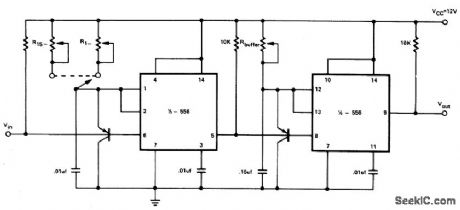
SPEED_WARNING_DEVICE
Published:2009/6/24 4:03:00 Author:May
View full Circuit Diagram | Comments | Reading(1221)
AF_POWER_OSCILLATOR
Published:2009/6/24 4:15:00 Author:Jessie

An LM386 audio power IC is set up as a feedback oscillator. Any supply from 6 to 12 V can be used. The circuit can drive a loudspeaker. (View)
View full Circuit Diagram | Comments | Reading(1198)
SPEED_ALARM
Published:2009/6/24 4:00:00 Author:May

Pulses from the distributor points are pas-sed through a current limiting resistor, rec-tified, and clipped at 4.7 volts. Via Q1 and the diode pump, a dc voltage proportional to engine rpm is presented to RV1; the sharp transfer characteristic of a CM0S gate, assisted by feedback, is used to enable the oscillator formed by the remaining half of the 4011. At the pre-set speed, a nonignorable tone emits from the speaker, and disappears as soon as the speed drops by three or four mph. (View)
View full Circuit Diagram | Comments | Reading(828)
TEMPERATURE_CONTROLLER
Published:2009/6/24 3:51:00 Author:May
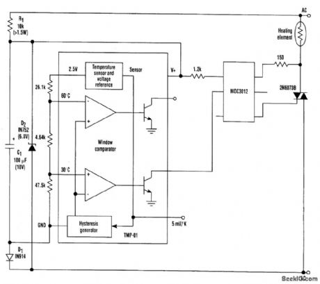
The temperature sensor/controller (the TMP-01) is a monolithic device whose low power allows it to operate with a simple half-wave rectified power supply directly from the ac line. Such an ar-rangement greatly simplifies the power-supply design requirement to the point of only needing a few low-cost components to provide a single +6-Vdc supply.The TMP-01 is essentially a therrrtostat on a chip. It includes a linear temperature sensor (5 mV/K), and also has two comparators that switch at externally determined set points. These set points are established by resistively dividing the internal 2.5-V reference to set appropriate voltages on the inputs to the comparators.One comparator is used in this circuit to turn on the heating element when the temperature drops below 30℃; it corresponds to a voltage of 1.52V on the comparator's input. (View)
View full Circuit Diagram | Comments | Reading(0)
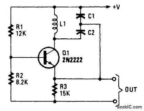
COLPITTS_OSCILLATOR
Published:2009/6/24 4:07:00 Author:Jessie
View full Circuit Diagram | Comments | Reading(1)
NE602_LOCAL_OSCILLATOR_CIRCUITS
Published:2009/6/24 4:05:00 Author:Jessie
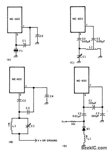
Local oscillator circuits for the NE602. (View)
View full Circuit Diagram | Comments | Reading(0)
OPTICAL_SAFETY_CIRCUIT_SWITCHES
Published:2009/6/24 3:55:00 Author:Jessie
Use of two LDR devices replaces the two vide light sources for the LDR devices. (View)
View full Circuit Diagram | Comments | Reading(458)
OPTOISOLATOR_AND_OPTOCOUPLER_INTERFACE_CIRCUITS
Published:2009/6/24 3:51:00 Author:Jessie

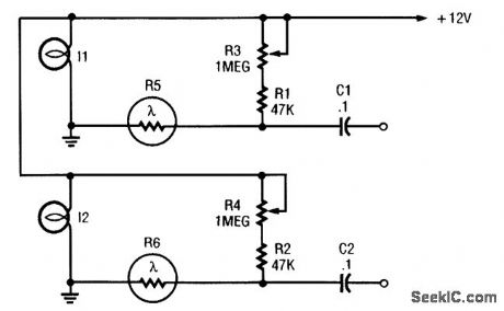
A circuit for isolating a variable resistor is shown. An optoisolator that has an LED and a photo-conductive cell (or photoresistor) is used. The current through the LED controls its brightness, which in turn determines the resistance between terminals A and B. The LED current is set by the voltage of the dc power supply and the value of the two resistors (R1 and R2). The fixed resistor (R1) is used to limit the current to a maximum of 20 mA (when the resistance of the potentiometer, R2, is set to zero ohms), otherwise, the LED might burn out. (View)
View full Circuit Diagram | Comments | Reading(3374)
OPTOCOUPLER_CIRCUITS
Published:2009/6/24 3:52:00 Author:Jessie
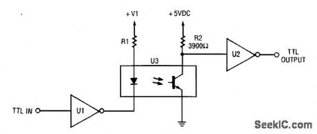
This circuit is a TTL-to-TTL isolator circuit. The driver circuit is an open-collector TTL inverter (U1). When the input is high, then the output of the inverter is low. Thus, when the input is high, the output of U1 grounds the cathode end of the LED and causes the LED to turn on. (View)
View full Circuit Diagram | Comments | Reading(1137)
MOTOR_DIRECTION_CONTROL
Published:2009/6/24 3:32:00 Author:May
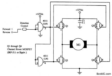
M1 is a small hobby dc motor. (View)
View full Circuit Diagram | Comments | Reading(1235)
LOW_VOLTAGE_dc_MOTOR_SPEED_CONTROLLER
Published:2009/6/24 3:27:00 Author:May
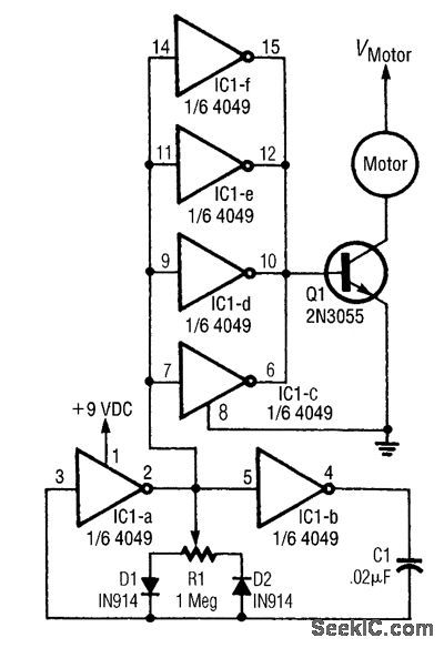
This circuit varies the duty cycle, rather than the voltage. The two diodes control the positive and negative halves of the capacitor's charging cycle. (View)
View full Circuit Diagram | Comments | Reading(582)
ANALOG_SWITCH_CIRCUIT_1
Published:2009/6/24 3:24:00 Author:May

View full Circuit Diagram | Comments | Reading(0)
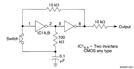
SIMPLE_SWITCH_DEBOUNCER
Published:2009/6/24 3:23:00 Author:May

Pressing S1 discharges C1 through R1, causing Q1 to cut off, forcing the output high. Once C1 is discharged below the VBE (ON) of Q1, switch bounce will have no effect on the output. (View)
View full Circuit Diagram | Comments | Reading(0)
SWITCH_DEBOUNCERS
Published:2009/6/24 3:22:00 Author:May

These circuits will cure problems caused by switch-contact bounce. The one shown in Fig.88-21A provides you a positive output pulse, and the one shown in Fig. 88-21B provides you a neg-ative output pulse. (View)
View full Circuit Diagram | Comments | Reading(0)
ALTERNATING_ON_OFF_CONTROL
Published:2009/6/24 3:21:00 Author:May
When the switch is closed, it causes a change in the state of pins 1 through 8. This will provide a toggle flip-flop action. (View)
View full Circuit Diagram | Comments | Reading(710)
GEIGER_COUNTER
Published:2009/6/24 3:21:00 Author:May
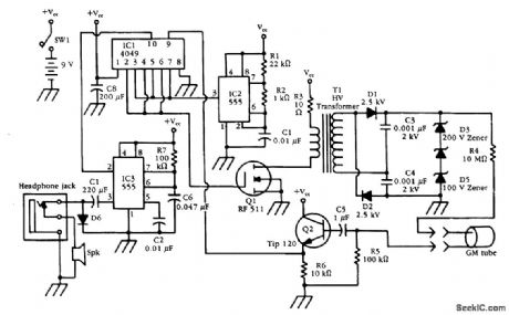
An HV generator (IC1, IC2, Q1, T1, and associated components) power a G-M tube. A pulse from the GM tube is interfaced through Q2 and IC1 to pulse generator IC3, which drives a speaker. (View)
View full Circuit Diagram | Comments | Reading(745)
TRIAC_MOTOR_CONTROL_CIRCUIT
Published:2009/6/24 3:23:00 Author:Jessie

An SCR-controlled ac motor control circuit. This is a full-wave circuit and is best used when the load remains constant. (View)
View full Circuit Diagram | Comments | Reading(4935)
SIMPLE_SWITCH_DEBOUNCER
Published:2009/6/24 3:23:00 Author:Jessie
Pressing S1 discharges C1 through R1, causing Q1 to cut off, forcing the output high. Once C1 is discharged below the VBE (ON) of Q1, switch bounce will have no effect on the output. (View)
View full Circuit Diagram | Comments | Reading(1158)
| Pages:170/312 At 20161162163164165166167168169170171172173174175176177178179180Under 20 |
Circuit Categories
power supply circuit
Amplifier Circuit
Basic Circuit
LED and Light Circuit
Sensor Circuit
Signal Processing
Electrical Equipment Circuit
Control Circuit
Remote Control Circuit
A/D-D/A Converter Circuit
Audio Circuit
Measuring and Test Circuit
Communication Circuit
Computer-Related Circuit
555 Circuit
Automotive Circuit
Repairing Circuit