Relay Control
Index 8
Wound rotor type motor reverse brake circuit
Published:2011/7/5 3:51:00 Author:John | Keyword: Wound rotor, motor
View full Circuit Diagram | Comments | Reading(1654)
Wound rotor induction motor manual and automatic serial reactor step-down start-up circuit
Published:2011/7/5 3:50:00 Author:John | Keyword: serial reactor, Wound rotor, induction motor
View full Circuit Diagram | Comments | Reading(2843)
Wound rotor induction motor ultilizing current variation starting circuit
Published:2011/7/5 3:49:00 Author:John | Keyword: Wound rotor, induction motor
View full Circuit Diagram | Comments | Reading(1629)
wound rotor induction motor serial reactor step-down starting circuit
Published:2011/7/4 23:49:00 Author:John | Keyword: wound rotor, induction motor, reactor
View full Circuit Diagram | Comments | Reading(2250)
Thermal relay overload protection circuit
Published:2011/7/5 4:04:00 Author:John | Keyword: Thermal relay

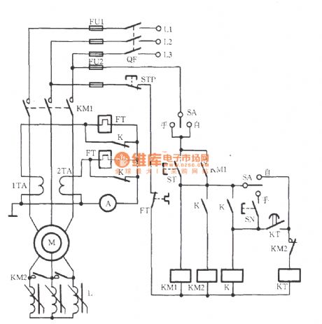
Thermal relay overload protection circuit can be applied to avoid the failure, which is as shown. FT is the thermal relay in the string for the circuit. When motor M is overloaded, internal heating elements of FT are heated. Then the bimetal pieces bend to promote the FT’s normally closed contacts to disconnect. Thus, the AC power contactor KM coil is off. The main contact KM is off to stop the motor M. at the end, the overload failure of the winding burn can be effectively eliminated. After the overload failure being removed, Reset button of the thermal relay is pressed as well as the starting button ST. Finally, the motor can start again.
(View)
View full Circuit Diagram | Comments | Reading(5802)
Vertical mill electrical control circuit
Published:2011/7/5 0:03:00 Author:John | Keyword: Vertical mill

The button ST is pressed to induct the KM1 coil circuit. When the pin 5-6 of KM1 is disconnected, HG is off; and when the pin 1~2 is connected, yellow light HY lights. This indicated that it is starting. The pin 7-8 of KM1 is disconnected to prevent KM2 from being powered under accidental circumstances. Thus, the interlock between KM1 and KM2 has been achieved. When the contact 3-4 of KM1 is closed, KM1 is self-locked. This is able to lead the timing relay KT to start to work. (SA’s contacts are connected), but also to close the middle relay K by electric pull. Then the contact 3 ~ 4 and contact 5 ~ 6 both close. As a result, the heating element in the hot relay circuit is in short, thus preventing motor M from FT’s malfunction while staring with high current.
(View)
View full Circuit Diagram | Comments | Reading(3861)
freezer and cooling pump interlock control circuit
Published:2011/7/5 0:07:00 Author:John | Keyword: freezer, cooling pump, interlock

The freezer and cooling pump interlock control circuit is as shown. It can be started through starting frozen pump, cooling pump and opening the freezer boot process. It can be stopped by the reverse process
(View)
View full Circuit Diagram | Comments | Reading(2136)
Delicate automatic rice cooker 2
Published:2011/7/5 0:38:00 Author:John | Keyword: rice cooker

PDF for related components can be downloaded.
BT13480508550S3P2289015
(View)
View full Circuit Diagram | Comments | Reading(1423)
Delicate automatic rice cooker 1
Published:2011/7/5 0:40:00 Author:John | Keyword: automatic rice cooker

PDF for related components can be downloaded.
BT13480508550HT46R47 (View)
View full Circuit Diagram | Comments | Reading(2768)
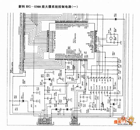
Shinco HG-5300 amplifier system control circuit (a)
Published:2011/7/4 10:59:00 Author:John | Keyword: amplifier system
View full Circuit Diagram | Comments | Reading(1068)
LED(relay) drive circuit diagram
Published:2011/6/30 13:45:00 Author:Sophia | Keyword: LED(relay), drive circuit

(View)
View full Circuit Diagram | Comments | Reading(725)
Automatic dimming curtain circuit
Published:2011/7/2 4:23:00 Author:John | Keyword: Automatic dimming curtain

When the outdoor light enhances, the interior light also enhances and the photodiode resistance becomes smaller. Then the point A’s potential rises to drive the output potential to rise on KD28’s pin 3. Besides, the potential on pin 5 decreases to drive the motor M to transfer. Afterwards, the curtain slowly closes until the indoor light weakens. The resistance of D increases until it is large enough to drive the bridge to be balanced again. Conversely, when there is less light, the motor M rotates reversely to drive the curtain to slowly open. C1 and R6 operate with delay effect. This can make the control process undergo gradually, thus being able to avoid motor’s repeated starting because of the accidentally opened curtain from wind blowing.
(View)
View full Circuit Diagram | Comments | Reading(1644)
combustible gas automatic ignition device circuit
Published:2011/7/2 3:37:00 Author:John | Keyword: combustible gas, automatic ignition device
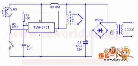
The device uses TWH8751 power electronic manifold to form a high voltage spark ignition device, which is made to be under the control of flame feedback optical signal. It also has the function to re-ignite after the turning off for some reason. If this device is compatible with other control circuit, the entire unit is able to achieve the automation of cooking. TWH8751, R1, C1 and others are used to constitute the square-wave generator. B2 is a booster, which can be the 12-inch ignition coil. Its primary stage uses 30 turns of 0.3mm enameled wire or output transformer in the tube radio with direct substitution.
(View)
View full Circuit Diagram | Comments | Reading(1096)
Herald M810 amplifier system control circuit( two)
Published:2011/6/5 0:02:00 Author:John | Keyword: amplifier

Herald M810 amplifier system control circuit( two) is shown below.
(View)
View full Circuit Diagram | Comments | Reading(595)
Optional frequency coefficient time delay circuit diagram
Published:2011/5/13 4:05:00 Author:Rebekka | Keyword: Optional frequency coefficient, time delay

Optional frequency coefficient time delay circuit diagram is shown as above. The circuit is composed of two 7-bit binary serial counters CC4024, controlled pulse source (gate 1, 2 components) and input, output control circuit. (View)
View full Circuit Diagram | Comments | Reading(654)
Positive and negative pulse delay circuit compoed of CD4013
Published:2011/5/12 6:33:00 Author:Rebekka | Keyword: Positive and negative pulse delay

In the digital circuits and automatic control circuit, sometimes you need to delay the inputed pulse signal for a while and then output the signal. This can accommodate the needs of post-level control circuit. One of the application scheme is to use the pulse delay circuit composed of CD4013. The positive and negative pulse delay circuit compoed of CD4013 is shown as above. (View)
View full Circuit Diagram | Comments | Reading(4555)
Relay measurment circuit diagram
Published:2011/3/20 22:56:00 Author:Ecco | Keyword: Relay measurment
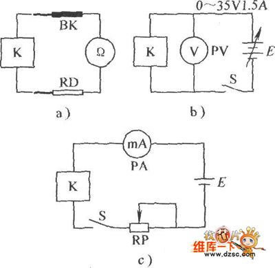
Relay measurment circuit diagram is as below:
(View)
View full Circuit Diagram | Comments | Reading(567)
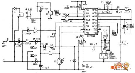
Based on HT7610A/HT7611A Relay Drive Circuit Diagram
Published:2011/3/21 4:18:00 Author:Nicole | Keyword: Relay Drive
View full Circuit Diagram | Comments | Reading(2603)
| Pages:8/8 12345678 |
Circuit Categories
power supply circuit
Amplifier Circuit
Basic Circuit
LED and Light Circuit
Sensor Circuit
Signal Processing
Electrical Equipment Circuit
Control Circuit
Remote Control Circuit
A/D-D/A Converter Circuit
Audio Circuit
Measuring and Test Circuit
Communication Circuit
Computer-Related Circuit
555 Circuit
Automotive Circuit
Repairing Circuit

