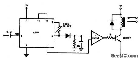
Relay Control
Index 2
ZERO_VOLTAGE_SWITCHING,SOLID_STATE_RELAY_WITH_ANTIPARALLEL_SCR_OUTPUT
Published:2009/7/8 22:51:00 Author:May
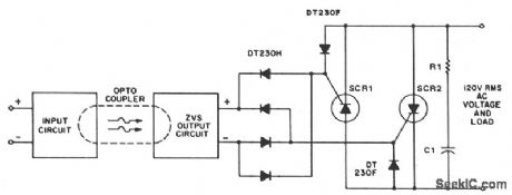
A higher line voltage can be used if the diode, varistor, ZVS, and power thyristor settings are at compatible levels. For applications beyond triac current ratings, antiparallel SCRs might be triggered by the ZVS network. (View)
View full Circuit Diagram | Comments | Reading(3321)
NORMALLY_OPEN_AND_NORMALLY_CLOSED_DC_SOLID_STATE_RELAYS
Published:2009/7/8 22:42:00 Author:May
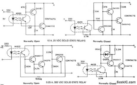
The phototransistor and photodarlington couplers act as dc relays in saturated switching at currents up to 5 mA and 50 mA, respectively. When higher currents or higher voltage capabilities are required, additional devices are required to buffer or amplify the photocoupler output. The addition of hysteresis to provide fast switching and stable pick-up and drop-out points can be easily implemented simultaneously.These circuits provide several approaches to implement the dc relay function and serve as practical, costeffective examples. (View)
View full Circuit Diagram | Comments | Reading(1695)
RF_ACTUATED_RELAY
Published:2009/7/7 8:08:00 Author:May
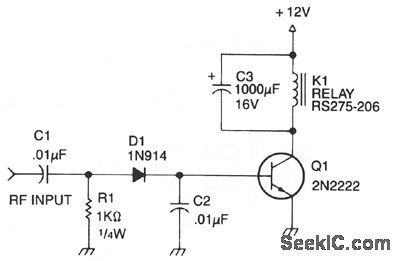
Automatic antenna switching or rf power indi-cation can be achieved with this circuit. Relay will key with less than 150 mW drive on 2 m. (View)
View full Circuit Diagram | Comments | Reading(1685)
LIGHT_CHANGE_SENSOR_DRIVES_RELAY
Published:2009/7/6 6:10:00 Author:May
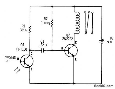
Capacitive coupling between phototransistor and bipolar transistor makes circuit respond only to interruptions or rapid changes in light while ignoring normal gradual changes in ambient light as caused by clouds or at sunrise. Relay pulls in when flash of light occurs and drops out when light is removed, Use Radio Shack 275-004 miniature relay.-F. M. Mims, Transistor Projects, Vol. 3, Radio Shack, Fort Worth, TX, 1975, p 69-74. (View)
View full Circuit Diagram | Comments | Reading(1855)
PHOTOTRANSISTOR_RELAY
Published:2009/7/6 6:07:00 Author:May
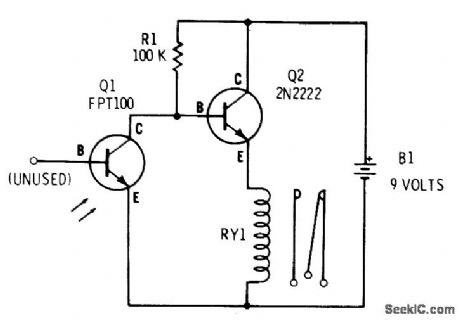
With phototransistor Q1 dark, R1 biases Q2 into conduction and miniature SPDT relay (Radio Shack 275-004) is energized. When light falls on Q1, Q2 is turned off and relay drops out. Battery drain is about 5 mA in darkness, dropping almost to 0 mA with light.-F. M. Mims, Transistor Projects, Vol. 3, Radio Shack, Fort Worth, TX, 1975, p 69-74. (View)
View full Circuit Diagram | Comments | Reading(2804)
INTEGRATED_SOLID_STATE_RELAY
Published:2009/7/5 22:19:00 Author:May

A complete zero-voltage switch solid-state relay contains an input circuit, an output circuit, and the power thyristor. The circuit illustrates a triac power thyristor with snubber circuit and GE-MOVR II Varistor transient over-voltage protection. The 22 ohm resistor shunts di/dt currents, passing through the bridge diode capacitances, from the triac gate, while the 100 ohm resistor limits surge and gate currents to safe levels. Although the circuits illustrated are for 120-V rms operation, relays that operate on 220 V require higher voltage ratings on the MOV, rectifier diodes, triac, and pilot SCR. The voltage divider that senses zero crossing must also be selected to minimize power dissipation in the transistor optisolator circuit for 220-V operation. (View)
View full Circuit Diagram | Comments | Reading(2795)
CARRIER_OPERATED_RELAY_
Published:2009/7/3 3:00:00 Author:May
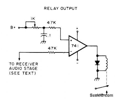
Relay is energized when carrier is present in FM receiver, to activate transmitter for repeater applications or turn on tape recorders, alarms, or other devices.Will work with either solid-state or tube-type receivers. Inverting (minus) input of opamp is connected directly to collector of audio preamp transistor or any other point having voltage change between signal and nosignal. If voltage change is in wrong direction, reverse leads to opamp input. Use 1K pot to set reference voltage so relay trips reliably on incoming signal.Relay can be reed-type drawing less than 75 mA.-S. Uhrig, The 5 Minute C0R, 73 Magazine, Dec. 1976, p 152-153. (View)
View full Circuit Diagram | Comments | Reading(3300)
FSK_OSCILLATOR_FOR_EKG_RELAY
Published:2009/7/3 2:49:00 Author:May

Used in satellite system for relaying electrocardiograms in digital form. Input consists of 8-bit words obtained in serial form from universal asynchronous receiver-transmitter. Uses 8038 function generator that is switched between two adjustable trimmer resistors giving independently ad justable discrete audio frequencies for mark and space. Output is phase-coherent even though switching does not necessarily take place at zero-crossing points of sine wave. 0peration is much like that of FSK RTTY.-D. Nelson, Medical Lbata Relay via Oscar Satellite, Ham Radio, April 1977, p 67-73. (View)
View full Circuit Diagram | Comments | Reading(1544)
TONE_DRIVEN_RELAY
Published:2009/6/30 2:13:00 Author:May

LM567 tone decoder will respond to frequency between 700 and 1500 Hz, determined by setting of 10K pot.When input of 100 mVRMS at preset frequency arrives, output of IC goes low and energizes relay through transistor. Tone can be obtained from audio oscillator or telephone Touch-Tone pad. Relay contacts can be used to turn desired device on or off.-J. A. Sandier, 9 Easy to Build Projects under $9, Modern Electronics, July 1978, p 53-56. (View)
View full Circuit Diagram | Comments | Reading(1574)
AUDIO_OPERATED_RELAY
Published:2009/6/30 2:05:00 Author:May

Addition of two general-purpose transistors to 555 timer gives audio-triggered relay that can be used for automatic recording of output of cttannel-monitorlng radio receiver or data from any audio link.Adjustable time delay R keeps control circuit actuated up to 5 s (determined by R and C) to avoid cycling relay during pauses in speech or dropouts in data. Q1 is NPN and Q2 is PNP. Attack time equals very short pullin time of 5-V reed relay K. Adjust 10K input pot just below point at which K pulls in when there is no audio input.-R. Taggart, Sound Operated Relay, 73 Magazine, Qct. 1977, p 114-11 (View)
View full Circuit Diagram | Comments | Reading(0)
SOUND_OPERATED_RELAY
Published:2009/6/30 1:36:00 Author:May

Output of about 1.8 m VRMS from crystal orceramic microphone will energize relay when sensitivity control R4 is at maximum. First two stages form high-gain RC-coupled AF amplifier, output of which is rec-tified by silicon diode X1. DC voltage developed across diode is applied to gate of Siliconix U183 FETwhich acts as DC amplifier driving Sigma 5F or equivalent relay. To ad just, short microphone terminals, set R4 for maximum sensitivity, then ad just R10 until relay opens.-R. P Turner, FET Circuits, Howard W. Sams, Indianapolis, IN, 1977, 2nd Ed., p 111-113. (View)
View full Circuit Diagram | Comments | Reading(1063)
CARRIER_OPERATED_RELAY
Published:2009/6/29 4:00:00 Author:May
View full Circuit Diagram | Comments | Reading(6)
TONE_ACTUATED_RELAY
Published:2009/6/29 3:57:00 Author:May
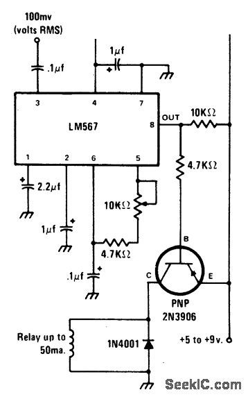
The circuit is built around the LM567 tone decoder IC that requires about 100 millivolts at its operating frequency. The frequency is set by a 10 K variable resistor and can be between 700 and 1500 Hz. When a tone at the set fre-quency is present, the 567's output goes low to energize a relay through a 2N3906 PNP transistor. (View)
View full Circuit Diagram | Comments | Reading(2445)
RELAY_DRIVER_
Published:2009/6/29 1:40:00 Author:May
View full Circuit Diagram | Comments | Reading(795)
TELEPHONE_RELAY
Published:2009/6/25 22:17:00 Author:May

Connected across the bell circuit of phone, this circuit closes a relay when the phone is ringing. Use the delay contacts to actuate any bell, siren, buzzer or lamp. (View)
View full Circuit Diagram | Comments | Reading(1078)
10_A_25_Vdc_SOLID_STATE_RELAYS
Published:2009/6/25 21:57:00 Author:May
View full Circuit Diagram | Comments | Reading(660)
SOUND_ACTIVATED_RELAY
Published:2009/6/25 21:19:00 Author:May

The device remains dormat (in an off con-dition) until some sound causes it to turn on. The input stage is a 741 operational amplifier connected as a noninverting follower audio amplifier. Gain is approximately 100. To increase gain raise the value of R2. The amplified signal is rectified and filtered to a dc level by R4. Then R5 is set to the audio level desired to activate the relay. (View)
View full Circuit Diagram | Comments | Reading(847)
AUDIO_OPERATED_RELAY
Published:2009/6/25 21:15:00 Author:May

Q1 and Q2 are general purpose transis-tors. The 10 K input pot is adjusted to a point just short of where Q1 turns on as indicated by K pulling in. K is any 5 V reed relay. With the values shown for R (100 K) and C (47 μF), timing values from.05 to slightly over 5 sec-onds can be achieved. B shows the addition o f a 22 K series resistor to the 10 K input pot if a 12 V supply is used. A suitable 12 V reed relay must be used at K. (View)
View full Circuit Diagram | Comments | Reading(0)
ULTRA_PRECISE_LONG_TIME_DELAY_RELAY
Published:2009/6/25 21:12:00 Author:May

Circuit NotesPredictable time delays from as low as 0.3 milliseconds to over 3 minutes are obtainable without resorting to a large value electrolytic-type timing capacitor. Instead, a stable low leakage paper or mylar capacitor is used and the peak point urrent of the timing UJT (Q1) is effectively reduced, so that a large value emit-ter resistor (R1) may be substituted. (View)
View full Circuit Diagram | Comments | Reading(827)
TONE_DECODER_WITH_RELAY_OUTPUT
Published:2009/6/25 20:48:00 Author:May
View full Circuit Diagram | Comments | Reading(0)
| Pages:2/8 12345678 |
Circuit Categories
power supply circuit
Amplifier Circuit
Basic Circuit
LED and Light Circuit
Sensor Circuit
Signal Processing
Electrical Equipment Circuit
Control Circuit
Remote Control Circuit
A/D-D/A Converter Circuit
Audio Circuit
Measuring and Test Circuit
Communication Circuit
Computer-Related Circuit
555 Circuit
Automotive Circuit
Repairing Circuit


