Relay Control
Index 6
Three-phase motor using proximity switch for automatically stopping inverting circuit
Published:2011/7/9 23:09:00 Author:Lucas | Keyword: Three-phase motor, proximity switch

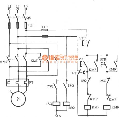
Just as shown in the circuit, 1SQ and 2SQ both are the non-contact new transistor proximity switch. And STF and STR are respectively forward and reverse button switches. When STF is pressed, KMF pulls to drive the motor to run forward. When it is to a qualified location, the metal plate on the machine rises to close the 1SQ and its internal contacts disconnect to drive the KMF coil to lose power. Then the motor stops. Compared to mechanical limit switch, non-contact transistor proximity switch has better performance, more reliability and longer service life.
(View)
View full Circuit Diagram | Comments | Reading(5174)
Three-phase motor button interlocking for switching circuit
Published:2011/7/9 22:49:00 Author:Lucas | Keyword: Three-phase motor, button

The three-phase motor button interlocking for switching circuit is shown in the figure. This circuit uses a composite button (this is that a button has a pair of normally opened contacts and a pair of normally closed contacts inside, thus ensuring the simultaneous action while being pressed), in order to achieve the button’s interlocking connection. When the motor is running forward, press the button STR to make the KMF lose electricity immediately. And the motor stops and run into the reverse immediately. And vice versa. This not only ensures the not simultaneous action of the reversing contactor KMF and KMR, but also ensure that it start in reverse by directly pressing reverse button rather than the stop button.
(View)
View full Circuit Diagram | Comments | Reading(2879)
Three-phase motor using the relay to prevent phase short circuit switching circuit
Published:2011/7/9 22:58:00 Author:Lucas | Keyword: Three-phase motor, relay

Just shown in the figure, a relay K is used to connect its coil to the main road. If the primary contact’s adhesion primary live line is with electricity or arc is not extinguished, K pulls to drive the normally closed contacts K to cut off STF and STR loop. So no matter what the forward or reverse button is pressed, the motor can not be started.
(View)
View full Circuit Diagram | Comments | Reading(1360)
Three-phase motor button and contactor dual-interlock switching circuit
Published:2011/7/9 11:17:00 Author:Lucas | Keyword: Three-phase motor, button, contactor, dual-interlock

Button contactor dual-interlock switching circuit is shown in the figure, which integrates the advantages of the button interlock and the contactor interlock.
(View)
View full Circuit Diagram | Comments | Reading(3007)
three-phase motor with △-starting and Y-running circuit
Published:2011/7/9 10:55:00 Author:Lucas | Keyword: three-phase motor
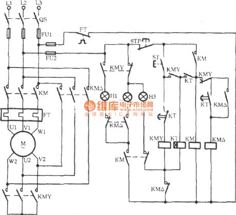
View full Circuit Diagram | Comments | Reading(800)
Liquid Level Controller (the 6th)
Published:2011/7/7 21:20:00 Author:Felicity | Keyword: Liquid Level Controller

Work of the circuit
The circuit consists of power circuit, liquid level detection circuit and control implementation circuit. (It is showed in picture 8-104.)
Power circuit consists of Knife switch Q, fuse FU, power transformer T, rectifier diode VDl-VD4, current limiting resistor Rl and R5, filter capacitor Cl and voltage diode VS.
Liquid level detection circuit consists of high level electrode H, low level I electrode and the main electrode M.
Control implementation circuit consists of transistor V, Relay K, time-base integrated circuit IC, diode VD5-VD8 and external RC components. (View)
View full Circuit Diagram | Comments | Reading(3230)
Liquid Level Controller (the 5th)
Published:2011/7/7 21:18:00 Author:Felicity | Keyword: Liquid Level Controller

Work of the circuit
The circuit consists of power circuit and level detection and control circuit. (It is showed in picture 8-103.)
Power circuit consists of knife switch Q, fuse FUl, FU2, the power switch Sl, the power transformer T, to bridge rectifier UR and filter capacitor C.
Level detection and control circuit consists of reed SAl, SA2, relay Kl, Pakistan, Journal of crystal tube VT, resistor R, AC contactor KM, thermal relay KR, control button S2, sweet and manual / automatic control switch S3.
(View)
View full Circuit Diagram | Comments | Reading(950)
Liquid Level Controller (the 4th)
Published:2011/7/7 21:17:00 Author:Felicity | Keyword: Liquid Level Controller

Work of the circuit
The circuit consists of power supply circuit, liquid level detection control circuit and indication starting control circuit. (It is showed in picture 8-102.)
Power supply circuit consists of Power transformer T, to bridge rectifier and filter capacitor C.
Liquid level detection control circuit consists of Liquid level detection electrode a-c, six non-gate IC IC (D1-D6), resistors Rl, R2, relay K, color light-emitting diodes VL and diode VD.
Indication starting control circuit consists of switch Q, fuse FUl-FU3, power switch Sl, manual / automatic control switch S2, the stop button S3, called the start button, AC contactors KM and thermal relays KR. (View)
View full Circuit Diagram | Comments | Reading(851)
Liquid Level Controller (the 3rd)
Published:2011/7/7 21:16:00 Author:Felicity | Keyword: Liquid Level Controller

Work of the circuit
The circuit consists of power circuit, liquid level detection circuit and control implementation circuit. (It is showed in picture 8-101.)
Power circuit consists of power transformer T, rectifier diode VDl-VD4 and filter capacitor C.
Liquid level detection circuit consists of high-level electrode A, low-level electrode B and the main electrode C.
Control implementation circuit consists of relay K, the control transistor V and AC contactor KM. (View)
View full Circuit Diagram | Comments | Reading(2067)
Liquid Level Controller (the 1st)
Published:2011/7/7 21:06:00 Author:Felicity | Keyword: Liquid Level Controller

Work of the circuit
The circuit consists of power circuit and level detection and control circuit. (It is showed in picture 8-99.)
Level detection and control circuit consists of detection electrodes,-c, control buttons S2, S3, resistors Rl-R4, transistor Vl, V2, light-emitting diode VLl, VL2, relay K, AC contactor KM and diode VD.
(View)
View full Circuit Diagram | Comments | Reading(944)
Wound rotor induction motor serial resistor step-down start-up circuit
Published:2011/7/6 9:13:00 Author:John | Keyword: Wound rotor, induction motor, serial resistor, 3KT

The circuit is as shown. Three time relays 1KT, 2KT and 3KT are used to automatically remove the rotor windings with three resistors of 1R, 2R and 3R. As a result, the purpose of automatically started to run has been achieved.
(View)
View full Circuit Diagram | Comments | Reading(2648)
greenhouse flower nursery humidity control with bird voice alarming circuit MS01-B
Published:2011/7/6 9:12:00 Author:John | Keyword: bird voice, greenhouse flower

The circuit is shown, which consists of humidity sensor, detection circuit, temperature indicator, comparator circuit, SCR control heating circuit, bird voice circuit and exchanging buck rectifier circuit. RH is the humidity sensor, which uses the MS01-B type. When the relative humidity inside the greenhouse changes from 20% to 90%, its resistance can range with a few kΩ to hundreds of kΩ.
(View)
View full Circuit Diagram | Comments | Reading(1029)
PWM micro-motor speed control circuit
Published:2011/7/6 9:12:00 Author:John | Keyword: micro-motor, PWM
View full Circuit Diagram | Comments | Reading(1566)
Gas leak sound and light alarming and auto exhausting device circuit
Published:2011/7/6 9:11:00 Author:John | Keyword: Gas leak, sound and light alarming, auto exhaust device

The circuit is as shown. It consists of the gas sensor, the relay exhaust fan control circuit, sound and light alarming circuit and AC buck rectifier circuit.
(View)
View full Circuit Diagram | Comments | Reading(726)
Gas leak automatic language alarming circuit
Published:2011/7/6 9:10:00 Author:John | Keyword: Gas, automatic language alarming, Gas leak

The circuit is as shown. It consists of the gas detection sensor, power switching control circuit, language voiced circuit and communication buck rectifier circuit. When the gas leak in the kitchen or living room reaches a certain concentration, the circuit will automatically start to exhaust through the exhaust fan. When the fan is started, a sentence said check for gas leak would be stated to warn the owner to pay attention to safety.
(View)
View full Circuit Diagram | Comments | Reading(963)
bridge and pick-up type speaker protection circuit
Published:2011/7/5 10:06:00 Author:John | Keyword: speaker
View full Circuit Diagram | Comments | Reading(3006)
Air pressure switch self-controlled circuit
Published:2011/7/5 10:05:00 Author:John | Keyword: Air pressure switch
The figure shows the air pressure switch self-controlled circuit, which uses the GYD-16 / C-type air pressure switch and contactor KM. The GYD shown in the figure is the air pressure switch. It directly controls the opening and closing action of AC contactor KM, thus being able to control the motor M to stop.
(View)
View full Circuit Diagram | Comments | Reading(680)
signal detection Y-△ starting circuit for preventing the coil from being disconnected
Published:2011/7/5 11:10:00 Author:John | Keyword: Y-△ starting circuit, coil
View full Circuit Diagram | Comments | Reading(870)
Zero sequence current phase protection circuit
Published:2011/7/6 4:46:00 Author:John | Keyword: Zero sequence current

The circuit is as shown, press the start button ST to lead the KM pulls. Then the motor M runs into normal operation. At this moment, three-phase load of the motor is balanced. Secondary current of the zero sequence current transformer TA is zero. The VT1 is off and the VT2 is inducted. The relay K (JR-4 type) pulls to lead the KM to be self-locked. When the phase is broken, current induced by TA’s secondary pole is rectified by the VD1, thus turning the VT1 from the deadline state to induction state. However, the VT2 is turned from the induction state to deadline state (VT2’s power supply is picked out from the winding around generator L on the KM coil, which is about 15 ~ 18V and used to power after being rectified by the VC).
(View)
View full Circuit Diagram | Comments | Reading(1109)
Zero sequence voltage off-phase protection circuit
Published:2011/7/6 5:01:00 Author:John | Keyword: off-phase protection

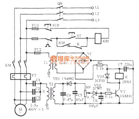
As shown in the figure, when the motor is within normal operation, the three-phase power supply is connected to three capacitors Y with the equal capacitance. Then potential of its contact E is 0V and the secondary side of transformer T2 is with no output voltage. As a result, when the VT is turned off, the K is released and its normally closing contacts are normally closed. And KM coils work properly. When any phase of the three-phase power supply is off, contact E values several volts due to the unbalanced three-phase. The voltage is gone through the transformer T2, VD1 rectifier, C4 and C5 filters, VD2 regulator, C6 and delay resistor R1. Afterwards, the voltage is added to the VT base to induct VT. K acts to cut the normally closing contacts of K. The KM circuit is cut off and the motor M stops working without electricity.
(View)
View full Circuit Diagram | Comments | Reading(1856)
| Pages:6/8 12345678 |
Circuit Categories
power supply circuit
Amplifier Circuit
Basic Circuit
LED and Light Circuit
Sensor Circuit
Signal Processing
Electrical Equipment Circuit
Control Circuit
Remote Control Circuit
A/D-D/A Converter Circuit
Audio Circuit
Measuring and Test Circuit
Communication Circuit
Computer-Related Circuit
555 Circuit
Automotive Circuit
Repairing Circuit


