
Basic Circuit
Index 413
The engine control circuit of Buick-Century 3.3L(3)
Published:2011/5/17 20:05:00 Author:Borg | Keyword: engine control circuit, Buick-Century
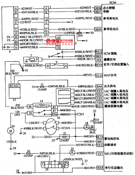
The engine control circuit of Buick-Century 3.3L(3)1-igniting switch; 2-air-conditioner fuse; 3-air-conditioner control switch; 4-air-conditioner high voltage switch; 5-air-conditioner low voltage switch; 6-engine/air-conditioner fuse; 7-air-conditioner clutch relay; 8-diode locked in bundles, about 3·8cm away from connector; 9-the right-rear ground connection of engine; 10-air-conditioner ground connection of compressor; 11-speed meter; 12-speed module tube pin D; 13-fun relay; 14-radiator fan; 15-P/S bracket ground connection. (View)
View full Circuit Diagram | Comments | Reading(909)
The engine control circuit of Buick-Century 3.3L(2)
Published:2011/5/17 19:52:00 Author:Borg | Keyword: engine control circuit, Buick-Century

Figure 6-28 The engine control circuit of Buick-Century 3.3L1-oil injection coil fuses; 2-oil injector; 3-igniting switch coil 8-lead connector; 4-stable speed module tube; 5-momentum steering pressure switch; 6-transmission ground connection; 7,14,18-instrument fuse; overheat indicator; 9-engine/air-conditioner fuse; 10-active carbon jar magnetic valve; 11-4T60-only transmission; 12-TCC electric magnetic valve; 13,17-brake switch; 3T40-only transmission (View)
View full Circuit Diagram | Comments | Reading(964)
The engine control circuit of Buick-Century 3.3L(1)
Published:2011/5/17 19:37:00 Author:Borg | Keyword: control circuit, Buick-Century

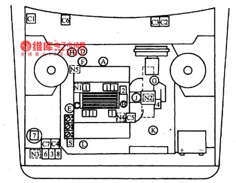
The engine control circuit of Buick-Century 3.3L is as shown in Figure 6-27 to Figure 6-30, whose sensors include: throttle position sensor; coolant temperature sensor, crankshaft position sensor; oxygen sensor, explosive sensor and air flow meter; and the sensors are here as transmission gear switches of input signals, momentum steering pressure switch, air-conditioner tube pressure switch and air-conditioner voltage switch.
Computer equipment: c1-engine computer; c2-diagnosis plug; c3-fault indicator; c4-computer/oil pump fuse (View)
View full Circuit Diagram | Comments | Reading(1023)
The seatbelt protection system circuit of Buick-Century
Published:2011/5/17 22:15:00 Author:Borg | Keyword: protection system, Buick-Century
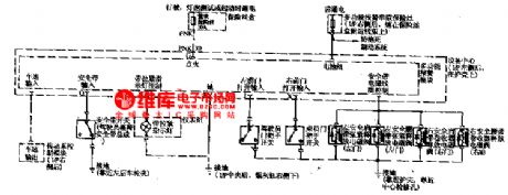
Usually, there are some warning systems, for example, when the igniting switch is connected but the seatbelt is off, and the doors are not closed well, the seatbelt warning lamp will flash, meanwhile, there are some buzzing from the clock warning; besides, some cars, such as Ford Taurus, which is fixed with auto seatbelt, when the door is open and the igniting switch is on, the seatbelt will automatically fix the driver in the chair along the chair track. If the driver want to get off, when he/she opens the door, the belt will go back to its former position, which is convenient for the driver to leave the seat.
(View)
View full Circuit Diagram | Comments | Reading(499)
The multiple warning system circuit of Buick-Century
Published:2011/5/17 21:09:00 Author:Borg | Keyword: warning system, Buick-Century
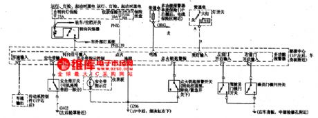
The multiple warning system is fixed on the left-rear side of the I/p, which is near the body panel, it can buzz or flash when in dangerous or abnormal conditions.When the speed is too high, seat belt is not fixed, the igniting key is in when the car is off, parking lamps or large lights are on, car doors are not closed well and steering indicator is in, etc, the system will warn the driver in time. The input signals are all kinds of switch and signal voltages; the power supply comes from general fuse(15A, behind the instrument plate).
(View)
View full Circuit Diagram | Comments | Reading(478)
The electric window circuit of Buick-Century
Published:2011/5/17 21:27:00 Author:Borg | Keyword: electric window, Buick-Century
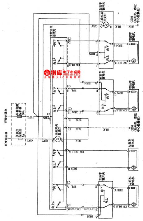
This circuit is the same with common cars, which has a general switch controlled by the driver, and there are separated switches controlled by passengers, when press head up , the glass will raise up, and vice versa. The elevation motor is a permanent micro D.C motor.
(View)
View full Circuit Diagram | Comments | Reading(781)
Typical Application Circuit of M50460-012P IC
Published:2011/5/16 8:44:00 Author:Michel | Keyword: Application Circuit, IC


 Typical Application Circuit
Remote control typical application circuit composed of M50460-012P IC is showed as above.Picture:Typical Application Circuit of M50460-012P IC (View)
View full Circuit Diagram | Comments | Reading(801)
The electric chair circuit of Buick-Century
Published:2011/5/17 21:18:00 Author:Borg | Keyword: chair circuit, Buick-Century
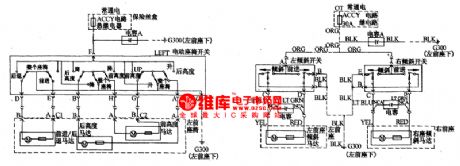
The positions of the driver or passenger chairs (front or back, high or low and the angle of the backrest)has a big affect on driving or passengers' comfort, passengers of different figures should adjust the position properly. The principle of the circuit is like to that of glass elevators.
(View)
View full Circuit Diagram | Comments | Reading(1662)
The auto-antenna circuit of Buick Century
Published:2011/5/17 8:53:00 Author:Borg | Keyword: auto-antenna, Buick Century
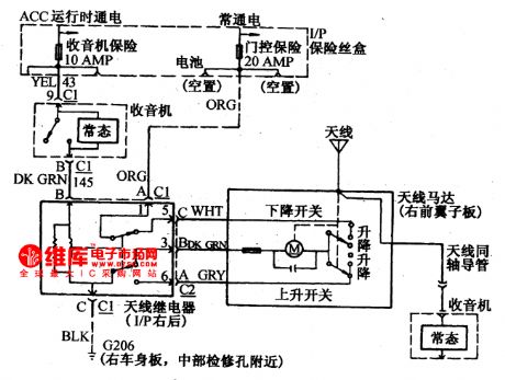

Usually, we raise or descend lifts by using reversing current of permanent-magnet direct current motors, and control the open circuit by course switches or overload protectors, when the antenna raise to the top or come down to the ground, the lift will stop automatically.
(View)
View full Circuit Diagram | Comments | Reading(586)
The circuit of voltages between wire points and connectors of Xiali 8A-FE engine
Published:2011/5/13 8:54:00 Author:Borg | Keyword: voltages, wire points, Xiali
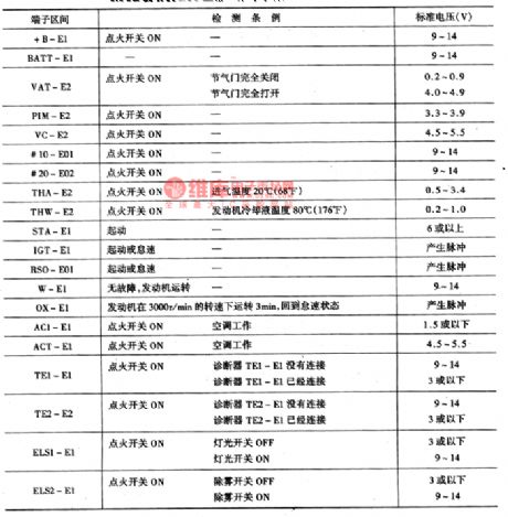
The potential values between the points are as shown in Figure 4.
Figure 4 voltage valuesbetween wire points and connectors of Xiali 8A-FEengine whileECU is normally working.
(View)
View full Circuit Diagram | Comments | Reading(440)
The codes of wire color in the circuit of Xiali cars
Published:2011/5/13 8:28:00 Author:Borg | Keyword: wire color, Xiali cars

The codes of wire color in the circuit of Xiali cars are as follows in Figure 5.
Figure 5. The codes of wire color in the circuit of Xiali cars
(View)
View full Circuit Diagram | Comments | Reading(412)
Inner Circuit Pane and Pin Function Circuitof M50462AP IC
Published:2011/5/16 8:30:00 Author:Michel | Keyword: Inner Circuit Pane, Pin Function, IC

Features and Functions
M50462AP IC generates remote control coding impulse,namely remote control command and outputs infrared remote control singal,which is used to remote control.This IC has three functions.
Firstly,it generates timing signal and remote carrier signal oscillator.Secondly,it generates 8 key sweep gate generators which appear at different time.Thirdly,it changes key codes(code value change) into teleswitch command encoder of remote command function code.
Pin Function and Data
M50462AP IC's plastic package adopts 24 pins dual inline type and the inner circuit pane and all pins' functions are showed as above. (View)
View full Circuit Diagram | Comments | Reading(749)
Typical Application Circuit of M50462AP IC
Published:2011/5/16 8:17:00 Author:Michel | Keyword: IC, Application Circuit


Typical Application Circuit
Typical application circuit of remote control emitter composed of M50462AP IC is showed as above.
Note:(23)pin of M50462AP IC outputs carrier signal and the signal amplifies via V001 which gives VD001 an impulse to launch infrared light signal.
Picture:Typical Application Circuit of M50462AP IC (View)
View full Circuit Diagram | Comments | Reading(731)
Inner Circuit Block Plan and Signal Flow Direction Circuit of M3727 and MP-209SP
Published:2011/5/16 21:37:00 Author:Michel | Keyword: Inner Circuit Block Plan, Signal Flow Direction Circuit

(View)
View full Circuit Diagram | Comments | Reading(658)
Pin Function Circuit of M50453-012P IC
Published:2011/5/16 9:10:00 Author:Michel | Keyword: Pin Function, Circuit, IC

Pin Function Circuit of M50453一012P IC
M50453一012P IC contains symbol signal generating circuit,line and field location signal processing circuit,system command and data decoder processing circuit.
Pin Function and Data
M50453一012P IC adopts 16 pins dual inline type packaging and its pins' functions are showed as above.
Picture:Pins' Functions ofM50453-012P IC
(View)
View full Circuit Diagram | Comments | Reading(1668)
Pin Function Circuit of M50450-023P IC
Published:2011/5/16 9:38:00 Author:Michel | Keyword: Pin Function Circuit, IC

Functions and Features
M50450一023P IC containsclockoscillator,character signal generating circuit and relative control circuit.
Pins' Functions and Data
M50450-023P IC adopts 20 pins dual inline type packaging and its pins' functions are showed as above.
Picture:Pins' Functions of M50450一023PIC (View)
View full Circuit Diagram | Comments | Reading(1525)
Typical Application Circuit of M50436-683SP IC
Published:2011/5/16 9:59:00 Author:Michel | Keyword: Typical Application Circuit, IC

(View)
View full Circuit Diagram | Comments | Reading(753)
Pin Function Circuit of M50143-006P IC
Published:2011/5/16 10:11:00 Author:Michel | Keyword: Pin Function Circuit, IC

Functions and Features
There are M50143-006P IC's clock oscillator circuit,serial data interface circuit,line and filed impulse generating circuit and character signal generating circuit etc.
Pins' Functions and Data
M50143-006P IC adopts 16 pins dual inline type packaging and its pins' functions are showed as above.
Picture:Pins' Functions of M50143-006P
(View)
View full Circuit Diagram | Comments | Reading(855)
crystal diode DDZX9697TS internal circuit
Published:2011/5/17 5:12:00 Author:chopper | Keyword: crystal diode, internal
View full Circuit Diagram | Comments | Reading(429)
Transistor delay circuit
Published:2011/5/17 19:13:00 Author:TaoXi | Keyword: Transistor, delay circuit
Transistor delay circuit (View)
View full Circuit Diagram | Comments | Reading(459)
| Pages:413/471 At 20401402403404405406407408409410411412413414415416417418419420Under 20 |
Circuit Categories
power supply circuit
Amplifier Circuit
Basic Circuit
LED and Light Circuit
Sensor Circuit
Signal Processing
Electrical Equipment Circuit
Control Circuit
Remote Control Circuit
A/D-D/A Converter Circuit
Audio Circuit
Measuring and Test Circuit
Communication Circuit
Computer-Related Circuit
555 Circuit
Automotive Circuit
Repairing Circuit
