Basic Circuit
Index 416
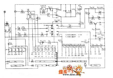
MF67 multimeter circuit diagram
Published:2011/5/13 1:17:00 Author:Nicole | Keyword: multimeter
View full Circuit Diagram | Comments | Reading(751)
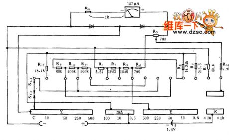
MF16 multimeter circuit diagram
Published:2011/5/13 1:17:00 Author:Nicole | Keyword: multimeter
View full Circuit Diagram | Comments | Reading(806)
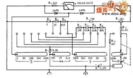
MF15 multimeter circuit diagram
Published:2011/5/13 1:16:00 Author:Nicole | Keyword: multimeter
View full Circuit Diagram | Comments | Reading(5303)
Internal circuit of diode DDZX5V2BTS
Published:2011/5/15 2:47:00 Author:John | Keyword: diode DDZX5V2BTS
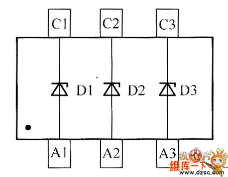
Internal circuit of diode DDZX5V2BTS is shown below.
(View)
View full Circuit Diagram | Comments | Reading(391)
Clock coupling circuit diagram(can be efficiently transmitted 5KHZ clock pulse)
Published:2011/5/13 3:38:00 Author:Ecco | Keyword: Clock coupling , efficiently , transmitted , 5KHZ , clock pulse
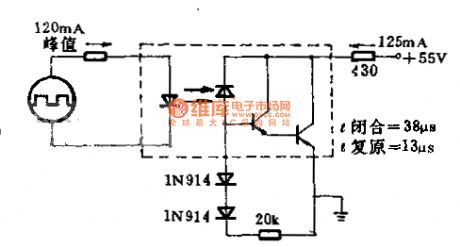
The circuit uses gallium arsenide infrared emitting diode and it is optically coupled to the silicon plane photoelectric mulriple pipe. Circuit requires insulation and it transfers 5KHz the clock pulse in high efficiency according to maximum rated voltage and current. Circuit uses photoelectric mulriple pipe which is led by the base to improve recovery time. The load is 400Ω. clock coupling circuit is shown as the chart (can be efficiently transmitted 5KHZ clock pulse).
(View)
View full Circuit Diagram | Comments | Reading(440)
Inverse proportion basic circuit diagram
Published:2011/5/13 3:54:00 Author:Ecco | Keyword: Inverse proportion, basic circuit

1. The basic circuit: Voltage series negative feedbackThe input end is virtual short, virtual-off The features:
Reverse side is the virtual ground, so the common mode input can be regarded as 0, the CMRR on the op amp requires low. The output resistance is small with a strong load capacity When it requires a large magnification, the feedback resistor is high, the stability is poor. If the required magnification is 100, R1 = 100K, Rf = 10M.
(View)
View full Circuit Diagram | Comments | Reading(519)
In-phase proportion circuit diagram
Published:2011/5/13 3:50:00 Author:Ecco | Keyword: In-phase , proportion
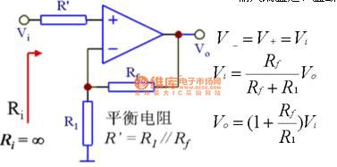
1. The basic circuit: Voltage series negative feedbackThe input end is virtual short, virtual-off The features: input resistance is high, output resistance is small, the load capacity is highV-= V + = Vi, so the common mode input is equal to the input signal, the common mode on the op amp's can suppress the ratio. (View)
View full Circuit Diagram | Comments | Reading(403)
High-performance medium-level circuit composed of L1590 and CX2501
Published:2011/5/13 1:34:00 Author:Rebekka | Keyword: High-performance medium-level

In the discharge circuit is high-performance. It is applicable to the medium-level which is particularly stringent required in making. It can also be used in medium-level of general receiver. The features of the circuit is: High gain, wide AGC range, high load capacity, high reliability and simple circuit. When the circuit is used in pairs, the amplitude frequency and phase frequency characteristics consistency of the two-way medium-level can achieve a very high target. (View)
View full Circuit Diagram | Comments | Reading(737)
Intelligent digital voltmeter circuit diagram composed of HI7159A
Published:2011/5/13 1:10:00 Author:Ecco | Keyword: Intelligent, digital voltmeter

Intelligent digital voltmeter circuit diagram composed of HI7159A 5 1 / 2dual integrating A / D converter with microprocessor is shown as the chart.
(View)
View full Circuit Diagram | Comments | Reading(2104)
Brushless DC motor principle chart
Published:2011/5/13 1:21:00 Author:Ecco | Keyword: Brushless DC motor, principle

1 - the main stator, 2 - the main rotor, 3 - sensor stator, 4 - sensor rotor, 5 - electronic reversing switch circuit
(View)
View full Circuit Diagram | Comments | Reading(663)
Adjustable voltage socket circuit diagram
Published:2011/5/13 0:46:00 Author:Ecco | Keyword: Adjustable voltage socket
View full Circuit Diagram | Comments | Reading(456)
The connection circuit diagram of DC watt-hour meter and additional resistors
Published:2011/5/13 2:42:00 Author:Ecco | Keyword: connection , DC , watt-hour meter , additional resistor

The connection circuit diagram of DC watt-hour meter and additional resistors is shown as the chart. This method is mainly used to make the measured degree of DC voltage and the voltage on the meter coil be fit.
(View)
View full Circuit Diagram | Comments | Reading(1464)
The connection circuit diagram of DC watt-hour meter by the shunt wiring
Published:2011/5/13 2:38:00 Author:Ecco | Keyword: connection , DC , watt-hour meter , shunt wiring

In the DC line, sometimes the operating current is higher, it does not connect to the meter directly.
(View)
View full Circuit Diagram | Comments | Reading(942)
The connection method circuit diagram between 3 ammeters and three-phase power
Published:2011/5/13 2:17:00 Author:Ecco | Keyword: connection method , 3 , ammeters , three-phase power
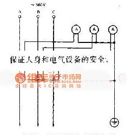
The connection method circuit diagram between 3 ammeters and three-phase power is shown as the chart. This methodology is commonly used in a wiring method, three current transformers must be grounded at one end to ensure the safety of persons and electrical equipment.
(View)
View full Circuit Diagram | Comments | Reading(1559)
High-speed 3:1 video multiplexer (MAX4188) circuit diagram
Published:2011/5/12 22:29:00 Author:Ecco | Keyword: High-speed , 3:1 , video , multiplexer
View full Circuit Diagram | Comments | Reading(714)
MF62 multimeter circuit diagram
Published:2011/5/12 21:48:00 Author:Nicole | Keyword: multimeter
View full Circuit Diagram | Comments | Reading(587)
MF63 multimeter circuit diagram
Published:2011/5/12 21:48:00 Author:Nicole | Keyword: multimeter
View full Circuit Diagram | Comments | Reading(941)
MF64 multimeter circuit diagram
Published:2011/5/12 21:49:00 Author:Nicole | Keyword: multimeter
View full Circuit Diagram | Comments | Reading(738)
MF66 multimeter circuit diagram
Published:2011/5/12 21:50:00 Author:Nicole | Keyword: multimeter
View full Circuit Diagram | Comments | Reading(2499)
MF90 multimeter circuit diagram
Published:2011/5/12 21:52:00 Author:Nicole | Keyword: multimeter
View full Circuit Diagram | Comments | Reading(625)
| Pages:416/471 At 20401402403404405406407408409410411412413414415416417418419420Under 20 |
Circuit Categories
power supply circuit
Amplifier Circuit
Basic Circuit
LED and Light Circuit
Sensor Circuit
Signal Processing
Electrical Equipment Circuit
Control Circuit
Remote Control Circuit
A/D-D/A Converter Circuit
Audio Circuit
Measuring and Test Circuit
Communication Circuit
Computer-Related Circuit
555 Circuit
Automotive Circuit
Repairing Circuit
