Index 13
Simple Water Detector-Circuit
Published:2013/11/21 20:47:00 Author:lynne | Keyword: Simple Water Detector Circuit

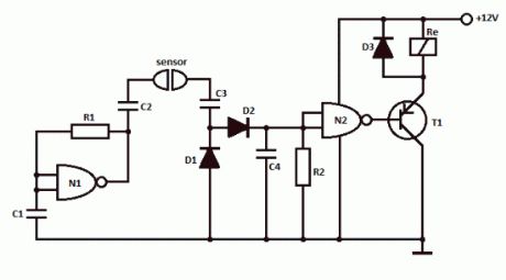
This simple water detector circuit uses alternative voltage in order to prevent the corrosion of the electrodes. It is easy to build and uses N1 as a trigger Schmitt gate which generate the AC. If between the electrodes is a electricity conductor, for example an aqueous solution, then because of the rectification action of D1 and D2, the C4 capacitor is charging.
When the capacitor voltage reaches switching threshold of the N2 trigger Schmitt, the relay will trigger and connect, for example a drain pump. The pump will be disconnected as soon as the electrodes won’t touch the liquid.
Simple water detector circuit schematic
Water detector componentsR1 = 470KR2 = 10M … 22MC1 … C4 = 2.2nFN1, N2 = 1/2 4093D1 … D3 = 1N4148T1 = pnp transistor (BC557) (View)
View full Circuit Diagram | Comments | Reading(1747)
Telephone Ringtone Generator Circuits
Published:2013/11/21 0:25:00 Author:lynne | Keyword: Telephone Ringtone Generator

This is a simple home telephone ringtone generator circuit which is built with applying only several electronic components / parts. It generates simulated telephone ringtone and requires only DC supply with 4.5V DC to 12V DC voltage.One may possibly use this circuit in ordinary intercom or phone-type intercom. The sound is pretty loud when this circuit is operated on +12V DC power supply. Even so, the volume of ring sound can be adjusted.
Ringtone generator circuit schematic
CD4060B is chosen to produce three kinds of pulses. Preset VR1 is fine-tuned to get 0.3125Hz pulses at pin 3 of IC1. At the same time, pulses obtainable from pin 1 will be of 1.25 Hz and 20 Hz at pin 14. The three output pins of IC1 are connected to base terminals of transistors T1, T2, and T3 through resistors R1, R2, and R3, respectively.
Working with a built-in oscillator-type piezobuzzer generates about 1kHz tone. In this particular circuit, the piezo-buzzer is turned ‘on’ and ‘off’ at 20 Hz for ring tone sound by transistor T3. 20Hz pulses are obtainable at the collector of transistor T3 for 0.4-second duration. Just after a time interval of 0.4 second, 20Hz pulses become again obtainable for another 0.4-second duration. This is followed by two seconds of nosound interval. Thereafter the pulse pattern repeats by itself. (View)
View full Circuit Diagram | Comments | Reading(1460)
Gas Leak Detector Circuit
Published:2013/11/21 0:22:00 Author:lynne | Keyword: Gas Leak Detector

Here is a gas leak detector circuit that detects the leakage of LPG gas and alerts the user through audio-visual indications. The circuit operates off a 9V PP3 battery. Zener diode ZD1 is used to convert 9V into 5V DC to drive the gas sensor module.
The gas leakage circuit uses the SEN-1327 gas sensor module from RhydoLABZ. Its output goes high when the gas level reaches or exceeds certain point. A preset in the module is used to set the threshold. Interfacing with the sensor module is done through a 4-pin SIP header.
Pin details of the gas sensor module are shown in Fig. 2. An MQ-6 gas sensor is used in the gas sensor module. The sensor can also be used to detect combustible gases, especially methane.
Gas leak detector schematic
Whenever there is LPG concentration of 1000 ppm (parts per million) in the area, the OUT pin of the sensor module goes high. This signal drives timer IC 555, which is wired as an astable multivibrator. The multivibrator basically works as a tone generator.
Output pin 3 of IC 555 is connected to LED1 and speaker-driver transistor SL100 through current-limiting resistors R5 and R4, respectively. LED1 glows and the alarm sounds to alert the user of gas leakage. The pitch of the tone can be changed by varying preset VR1. Use a suitable heat-sink for transistor SL100.
google_ad_client= ca-pub-9265205501290597 ;google_ad_slot= 6648404198 ;google_ad_width=336;google_ad_height=280;