Basic Circuit
Sine to Rectangular Wave Conversion Circuits
Published:2013/11/12 19:55:00 Author:lynne | Keyword: Sine to Rectangular Wave Conversion Circuits | From:SeekIC

We have already given many posts on Op-Amp circuits. But the list of applications of Op-Amp will be keep on going. The best Op-Amp circuit which is used to convert sine waveform into rectangular waveform is the schmitt trigger circuit.
To avoid the false triggering, a positive feedback is used in a comparator circuit of an Op-Amp. Thus the comparator with positive feedback is called Schmitt trigger or regenerative comparator. The inverting schmitt trigger mode produces opposite polarity output. This isfed back to the non-inverting input which is of same polarity as that of output. This ensures positive feedback.
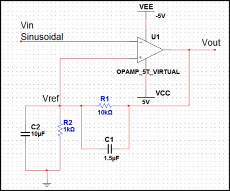
The above shown schematic is the sine to rectangular conversion circuit. For proper conversion of input signal from sine to rectangular, the input must be large enough to pass through both the tripping voltages.
Practically sometimes a capacitor C1 is connected in parallel with R1, as shown in the above schematic. The stray capacitance C2 forms the bypass circuit with R2. The use of speed-up capacitor C1 across R1 eliminates the effect of stray capacitance C2. Without speed-up capacitor, the stray capacitance C2 is required to be charged before the non-inverting input voltage changes. The speed-up capacitor used supplies the necessary charge to C2. For neutralizing the effect of stray capacitance, the minimum value of speed-up capacitor must be,
C1(min) = (R2/R1) C2.
When C1 is selected is greater than C1(min) then the switching of the output is very fast.
The frequency of the output of the Schmitt trigger is same as the frequency of the input signal.
The peak to peak value of the output rectangular waveform is approximately 2Vsat.
Reprinted Url Of This Article:
http://www.seekic.com/circuit_diagram/Basic_Circuit/Sine_to_Rectangular_Wave_Conversion_Circuits.html
Print this Page | Comments | Reading(3)

Article Categories
power supply circuit
Amplifier Circuit
Basic Circuit
LED and Light Circuit
Sensor Circuit
Signal Processing
Electrical Equipment Circuit
Control Circuit
Remote Control Circuit
A/D-D/A Converter Circuit
Audio Circuit
Measuring and Test Circuit
Communication Circuit
Computer-Related Circuit
555 Circuit
Automotive Circuit
Repairing Circuit
Code: