Basic Circuit
Metronome
Published:2013/11/3 20:37:00 Author:lynne | Keyword: Metronome Circuit | From:SeekIC

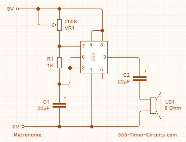
This circuit uses the 555 timer in an Astable operating mode and generates a continuous output via Pin 3 in the form of a square wave. This is then passed through the 22?F electrolytic capacitor to create a smooth oscillation which then creates the 'toc-toc' sound. The speed of the output is controlled by the 250K Potentiometer (VR1). Schematic
Parts List 1x - NE555 Bipolar Timer1x - 1K Resistor (1/4W) 2x - 22?F Electrolytic Capacitor (16V)1x - 250K Potentiometer1x - Loudspeaker (8 Ohm)1x - 9V Voltage Battery
Reprinted Url Of This Article:
http://www.seekic.com/circuit_diagram/Basic_Circuit/Metronome.html
Print this Page | Comments | Reading(3)

Article Categories
power supply circuit
Amplifier Circuit
Basic Circuit
LED and Light Circuit
Sensor Circuit
Signal Processing
Electrical Equipment Circuit
Control Circuit
Remote Control Circuit
A/D-D/A Converter Circuit
Audio Circuit
Measuring and Test Circuit
Communication Circuit
Computer-Related Circuit
555 Circuit
Automotive Circuit
Repairing Circuit
Code: