
Automotive Circuit
Index 116
XSARA steering lamp circuit diagram
Published:2011/4/24 20:45:00 Author:muriel | Keyword: XSARA, steering lamp

XSARA steering lamp circuit diagram is as shown
(View)
View full Circuit Diagram | Comments | Reading(504)
XSARA headlamp circuit diagram
Published:2011/4/24 20:39:00 Author:muriel | Keyword: XSARA, headlamp

XSARA headlamp circuit diagram is as shown
(View)
View full Circuit Diagram | Comments | Reading(498)
GUANGZHOU Fit windshield wiper and scrubber circuit diagram
Published:2011/4/24 20:31:00 Author:muriel | Keyword: GUANGZHOU Fit , windshield wiper, scrubber

GUANGZHOU Fit windshield wiper and scrubber circuit diagram is as shown
(View)
View full Circuit Diagram | Comments | Reading(720)
GUANGZHOU HONDA Accord engine circuit diagram
Published:2011/4/24 20:24:00 Author:muriel | Keyword: GUANGZHOU HONDA Accord, engine

GUANGZHOU HONDA Accord engine circuit diagram is as shown
(View)
View full Circuit Diagram | Comments | Reading(491)
GUANGZHOU Fit motor-driven rearview mirror circuit diagram
Published:2011/4/24 20:33:00 Author:muriel | Keyword: GUANGZHOU Fit, motor-driven rearview mirror

GUANGZHOU Fit motor-driven rearview mirror circuit diagram is as shown
(View)
View full Circuit Diagram | Comments | Reading(427)
GUANGZHOU Fit motor-driven car window circuit diagram
Published:2011/4/24 20:34:00 Author:muriel | Keyword: GUANGZHOU Fit, motor-driven car window
GUANGZHOU Fit motor-driven car window circuit diagram is as shown
(View)
View full Circuit Diagram | Comments | Reading(411)
XSARA loudspeaker circuit diagram
Published:2011/4/24 20:41:00 Author:muriel | Keyword: XSARA, loudspeaker

XSARA loudspeaker circuit diagram is as shown
(View)
View full Circuit Diagram | Comments | Reading(496)
GUANGZHOU Fit entrance light control system circuit diagram
Published:2011/4/24 20:36:00 Author:muriel | Keyword: GUANGZHOU Fit , entrance light control system
GUANGZHOU Fit entrance light control system circuit diagram is as shown
(View)
View full Circuit Diagram | Comments | Reading(492)
Variable-Tone Signal Generating Circuit
Published:2011/4/22 21:40:00 Author:Sue | Keyword: Variable-Tone, Signal, Generating
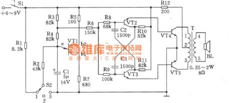
Variable-tone signal generating circuit can be used in making different types of alarms, and can also in toys which will bring about a lot of fun. As seen in the figure, this circuit comprises relaxation oscillatory composed of unijunction transistor VT1, multivibrator composed of VT2, VT3, and B-type push pull power amplifier composed of VT4, VT5. The selection of component is as follows.
VT1: Double-base diode BT33C, the direct current resistance RBB of which between b1 and b2 should be 3~10kΩ.
VT2,VT3: 9013,50≤β≤85.
VT4,VT5: 3DGl28,50≤β≤65.
(In order to guarantee the accuracy of frequency, the parameters of geminate transistors VT2 and VT3, VT4 and VT5 should be as consistent as possible.)
Power switch S1: KNX(1×1).
Selected switch S2: KZX-1-3W1D(band switch).
Audio transformer T: can-type ferrite MTT22, high-intensity enamelled wire L1-2ΦO.13mm, coiled by 380 turns; high-intensity enamelled wire L2-3ΦO.13mm, coiled by 380 turns; high-intensity enamelled wire L4-5Φ0.19mm, coiled by 46 turns.
Resistance R12: 1/2 WRJ-type
Other resistances: 1/8WRJ-type. (View)
View full Circuit Diagram | Comments | Reading(415)
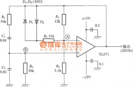
Wien Bridge Oscillator Circuit
Published:2011/4/22 20:33:00 Author:Sue | Keyword: Wien Bridge, Oscillator
View full Circuit Diagram | Comments | Reading(2705)
Terman Oscillator Circuit
Published:2011/4/22 20:42:00 Author:Sue | Keyword: Terman, Oscillator
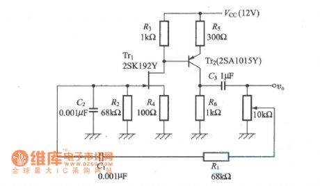
In Wien Bridge Circuit, connect J-FET between resistance R3 and R4, then replace operational amplifier with transistor. Circuit made in this way is called Terman oscillator circuit. (View)
View full Circuit Diagram | Comments | Reading(430)
T-Type Bridge Oscillator Circuit
Published:2011/4/22 20:48:00 Author:Sue | Keyword: T-Type Bridge, Oscillator

View full Circuit Diagram | Comments | Reading(629)
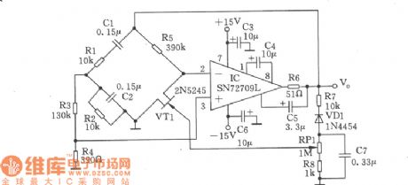
2.5kHz Wien Bridge Signal Generator Circuit
Published:2011/4/22 22:17:00 Author:Sue | Keyword: 2.5kHz, Wien Bridge, Signal, Generator
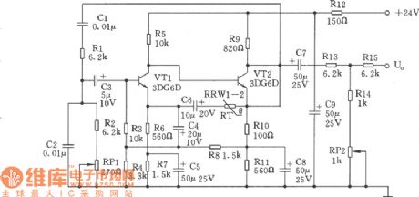
This signal generator is a kind of RC Wien Bridge oscillator Circuit. As seen in the figure, secondary direct-coupling amplifier is composed of triode VT1 and VT1. The input is in a form of bootstrap, making the input impedance much higher to reduce effects on phase-shifting circuit RC. As to the T-type attenuator connected to the output terminal, on one hand, it can meet the demands of output impedance, on the other hand it can reduce the effects that loads have on RC. In this case, the frequency stability of the oscillator depends on that of RC. Because of low-temperature coefficient of RC, the frequency of this oscillator is stable(25℃±15℃, change range ≤±5Hz). (View)
View full Circuit Diagram | Comments | Reading(547)
Wien Bridge Sine Wave Generator I Circuit
Published:2011/4/22 22:29:00 Author:Sue | Keyword: Wien Bridge, Sine Wave, Generator
View full Circuit Diagram | Comments | Reading(438)
Wien Bridge Sine Wave Generator II Circuit
Published:2011/4/22 22:31:00 Author:Sue | Keyword: Wien Bridge, Sine Wave, Generator
View full Circuit Diagram | Comments | Reading(443)
Wien Bridge Sine Wave Generator III Circuit
Published:2011/4/22 22:31:00 Author:Sue | Keyword: Wien Bridge, Sine Wave, Generator
View full Circuit Diagram | Comments | Reading(478)
Weak Pulse Signal Amplifier Circuit
Published:2011/4/23 3:53:00 Author:Joyce | Keyword: Weak, Pulse, Signal Amplifier
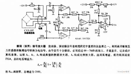
The signals of flexible and carotid artery is one of important information sources in pathological researches. The electrical signals,which are changed from pulse signals by high sensitivity pressure sensor signals is very weak, and it can be displayed, recorded or acquired by the computer only via amplification through 69-70dB . Op-amp A1, A2, A3 constitute the typical data amplifier,and A4 forms proportional amplifier. Op-amp F324,which is high gain and low power consumption is used here.
(View)
View full Circuit Diagram | Comments | Reading(609)
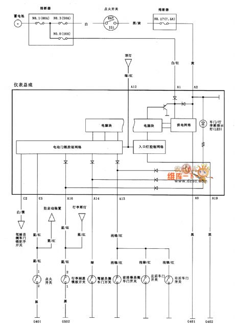
Yueda KIA Combination Instruments And Warning Lights Circuit
Published:2011/4/23 10:02:00 Author:Robert | Keyword: Yueda, KIA, Combination Instruments, Warning Lights
Yueda KIA Combination Instruments And Warning Lights Circuit is shown above. (View)
View full Circuit Diagram | Comments | Reading(467)
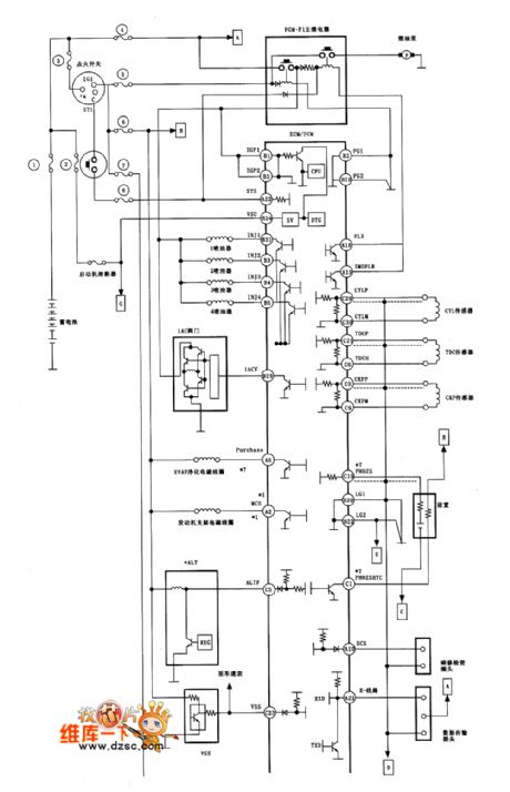
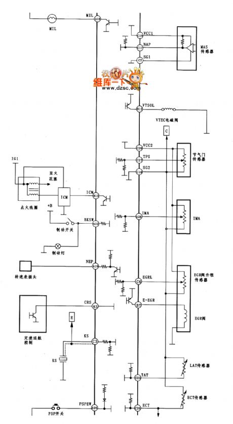
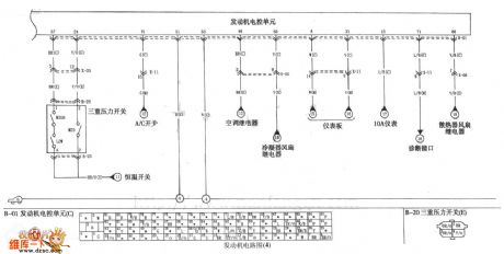
Yueda KIA Engine Electric Control Unit Circuit
Published:2011/4/24 6:19:00 Author:Robert | Keyword: Yueda KIA, Engine, Electric Control Unit

Yueda KIA Enging Electric Control Unit Circuit is shown above. (View)
View full Circuit Diagram | Comments | Reading(459)
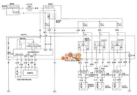
Yueda KIA Starting And Charging System Circuit
Published:2011/4/24 6:32:00 Author:Robert | Keyword: Yueda KIA, Starting And Charging System
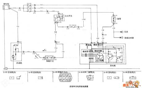
Yueda KIA Starting And Charging System Circuit is shown above. (View)
View full Circuit Diagram | Comments | Reading(532)
| Pages:116/164 At 20101102103104105106107108109110111112113114115116117118119120Under 20 |
Circuit Categories
power supply circuit
Amplifier Circuit
Basic Circuit
LED and Light Circuit
Sensor Circuit
Signal Processing
Electrical Equipment Circuit
Control Circuit
Remote Control Circuit
A/D-D/A Converter Circuit
Audio Circuit
Measuring and Test Circuit
Communication Circuit
Computer-Related Circuit
555 Circuit
Automotive Circuit
Repairing Circuit