Automotive Circuit
Variable-Tone Signal Generating Circuit
Published:2011/4/22 21:40:00 Author:Sue | Keyword: Variable-Tone, Signal, Generating | From:SeekIC

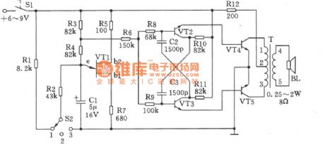
Variable-tone signal generating circuit can be used in making different types of alarms, and can also in toys which will bring about a lot of fun. As seen in the figure, this circuit comprises relaxation oscillatory composed of unijunction transistor VT1, multivibrator composed of VT2, VT3, and B-type push pull power amplifier composed of VT4, VT5. The selection of component is as follows.
VT1: Double-base diode BT33C, the direct current resistance RBB of which between b1 and b2 should be 3~10kΩ.
VT2,VT3: 9013,50≤β≤85.
VT4,VT5: 3DGl28,50≤β≤65.
(In order to guarantee the accuracy of frequency, the parameters of geminate transistors VT2 and VT3, VT4 and VT5 should be as consistent as possible.)
Power switch S1: KNX(1×1).
Selected switch S2: KZX-1-3W1D(band switch).
Audio transformer T: can-type ferrite MTT22, high-intensity enamelled wire L1-2ΦO.13mm, coiled by 380 turns; high-intensity enamelled wire L2-3ΦO.13mm, coiled by 380 turns; high-intensity enamelled wire L4-5Φ0.19mm, coiled by 46 turns.
Resistance R12: 1/2 WRJ-type
Other resistances: 1/8WRJ-type.
Reprinted Url Of This Article:
http://www.seekic.com/circuit_diagram/Automotive_Circuit/Variable_Tone_Signal_Generating_Circuit.html
Print this Page | Comments | Reading(3)

Article Categories
power supply circuit
Amplifier Circuit
Basic Circuit
LED and Light Circuit
Sensor Circuit
Signal Processing
Electrical Equipment Circuit
Control Circuit
Remote Control Circuit
A/D-D/A Converter Circuit
Audio Circuit
Measuring and Test Circuit
Communication Circuit
Computer-Related Circuit
555 Circuit
Automotive Circuit
Repairing Circuit
Code: