
Automotive Circuit
Index 114
SHANGHAI GM BUICK(Royaum) saloon car multifunction display screen circuit diagram
Published:2011/4/21 21:41:00 Author:muriel | Keyword: SHANGHAI GM BUICK(Royaum) , saloon car, multifunction display screen

Figure SHANGHAI GM BUICK(Royaum) saloon car multifunction display screen circuit diagram (View)
View full Circuit Diagram | Comments | Reading(480)
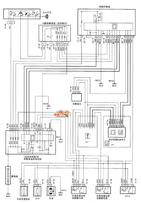
DONGFENG CITROEN Xsars starter and generator(automatic transmission) circuit diagram
Published:2011/4/24 21:39:00 Author:muriel | Keyword: DONGFENG CITROEN Xsars, starter, generator(automatic transmission)

DONGFENG CITROEN Xsars starter and generator(automatic transmission) circuit diagram is as shown
(View)
View full Circuit Diagram | Comments | Reading(1366)
DONGFENG CITROEN Xsars fuel injector and ignition system(manual transmission) circuit diagram
Published:2011/4/24 21:39:00 Author:muriel | Keyword: DONGFENG CITROEN Xsars, fuel injector , ignition system(manual transmission)

DONGFENG CITROEN Xsars fuel injector and ignition system(manual transmission) circuit diagram is as shown
(View)
View full Circuit Diagram | Comments | Reading(1592)
DONGFENG CITROEN Xsars fuel injector and ignition system(automatic transmission) circuit diagram
Published:2011/4/24 21:38:00 Author:muriel | Keyword: DONGFENG CITROEN Xsars , fuel injector, ignition system(automatic transmission)

DONGFENG CITROEN Xsars fuel injector and ignition system(automatic transmission) circuit diagram is as shown
(View)
View full Circuit Diagram | Comments | Reading(1185)
DONGFENG CITROEN Xsars cooling system(manual transmission) circuit diagram
Published:2011/4/24 21:37:00 Author:muriel | Keyword: DONGFENG CITROEN Xsars , cooling system(manual transmission)

DONGFENG CITROEN Xsars cooling system(manual transmission) circuit diagram is as shown
(View)
View full Circuit Diagram | Comments | Reading(643)
DONGFENG CITROEN Xsars cooling system(automatic transmission) circuit diagram
Published:2011/4/24 21:37:00 Author:muriel | Keyword: DONGFENG CITROEN Xsars, cooling system(automatic transmission)
DONGFENG CITROEN Xsars cooling system(automatic transmission) circuit diagram is as shown
(View)
View full Circuit Diagram | Comments | Reading(771)
DONGFENG CITROEN XSARA automatic transmission circuit diagram
Published:2011/4/24 20:57:00 Author:muriel | Keyword: DONGFENG CITROEN XSARA, automatic transmission
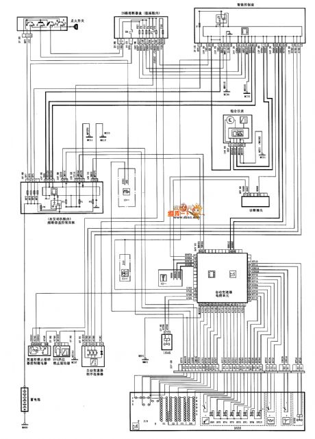
DONGFENG CITROEN XSARA automatic transmission circuit diagram is as shown
(View)
View full Circuit Diagram | Comments | Reading(2811)
DONGFENG CITROEN Xsars fog lamp circuit diagram
Published:2011/4/24 21:38:00 Author:muriel | Keyword: DONGFENG CITROEN Xsars , fog lamp
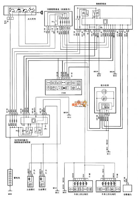
DONGFENG CITROEN Xsars fog lamp circuit diagram is as shown
(View)
View full Circuit Diagram | Comments | Reading(596)
DONGFENG CITROEN Xsars width lamp circuit diagram
Published:2011/4/24 21:38:00 Author:muriel | Keyword: DONGFENG CITROEN Xsars, width lamp

DONGFENG CITROEN Xsars width lamp circuit diagram is as shown
(View)
View full Circuit Diagram | Comments | Reading(512)
1kHz Wien Bridge Signal Generator Circuit Composed of LM358
Published:2011/4/24 20:50:00 Author:Sue | Keyword: 1kHz Wien Bridge, Signal, Generator
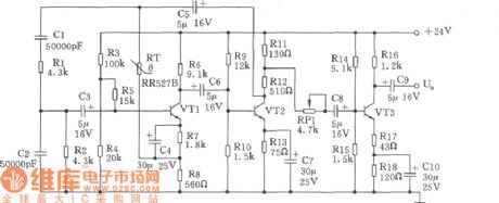
As seen in the figure is 1kHz signal generator composed of components such as double operational amplifier LM358, Rl~R15, Cl~C5 and so on. The 1kHz weak signal generated from Wien Bridge(C2、C3、R4 and R6) is amplified by A1, and then is buffer amplified by operational amplifier A2 and A3. These two OPRAMs have the opposite output, making a double-end balanced output out of a single-end one. (View)
View full Circuit Diagram | Comments | Reading(1560)
Electronic Tuner Circuit Composed of CC4040
Published:2011/4/22 20:30:00 Author:Sue | Keyword: Electric, Tuner,
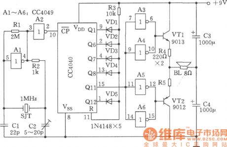
As seen in the figure is the electronic tuner circuit. It can generate International standarded A-tone of 440Hz and can be used as tuner for band. (View)
View full Circuit Diagram | Comments | Reading(798)
Multiple Sound Generator Circuit Composed of HT2880
Published:2011/4/21 23:07:00 Author:Sue | Keyword: Multiple, Sound, Generator

This circuit is able to generate 8 kinds of sounds: 2 kinds of machine guns sound, 2 kinds of bomb sound, dual-tone melody, game sound, animal sound and rifle sound. These sounds can be played by thumb-rotated switch S2 and a push-button switch. HT2880 is ROM chip of a large scale integrated circuit CMOS. In the circuit, transistor VT1 and VT2 are linked into Darlington geminate transistor to amplify signals output from the fourth terminal. (View)
View full Circuit Diagram | Comments | Reading(3405)
Homemade Simulated Gunshot Generator Circuit
Published:2011/4/22 20:27:00 Author:Sue | Keyword: Homemade, Simulated, Gunshot, Generator
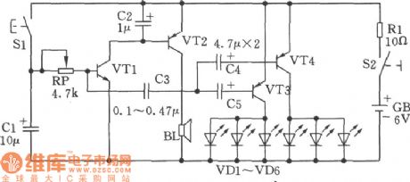
Complementary audio oscillator composed of two transistors can be used as simulated gunshot generator, and the homemade gunshot is very realistic with lingering sound. As seen in the figure, the selections of components are as follows: Triode VT1,VT2: 9014, β=85-115; VT3,VT4: 9015, β=65-85. S1: AN4; S2: KN3. Light emitting diode VD1~VD6: BT201(other types can be used, but luminotrons with low forward voltage and high luminous efficiency are better). Cell GB: 4F22DC6V laminated cells. Loudspeaker BL: 8Ω 0.25W. (View)
View full Circuit Diagram | Comments | Reading(1033)
Long Period Connected/Disconnected Multivibrator Circuit
Published:2011/4/21 21:03:00 Author:Sue | Keyword: Long Period, Connected/Disconnected, Multivibrator
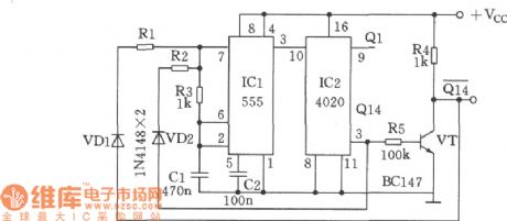
Multivibrator composed of 555 Timer IC can adjust the frequency and duty cycle separately, but when connected/disconnected period is long, a large capacitor is needed. As seen in the figure, however, without a large capacitor, adjustable connected/disconnected period can be realised, with the longest period reaching several hours. A 14-grade binary counter CD4020 is used to count the divided frequency, while the output terminals of CD4020, Q14 and Q14, are connected to R1 and R2 on the rising and falling edge, to output independent connected and disconnected period. The output terminal Q1 can be used to indicate the output of lasting periods. when R2=100k, Ton≈5minutes; when R1=1M, Toff≈50minutes. (View)
View full Circuit Diagram | Comments | Reading(617)
Mono-stable Multivibrator Circuit Composed of 74HCT221 with Variable Duty Cycle
Published:2011/4/21 20:54:00 Author:Sue | Keyword: Mono-stable, Multivibrator, Variable Duty Cycle
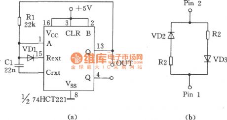
As seen in the figure is the mono-stable multivibrator composed of 74HCT221 with variable duty cycle. Capacitor C is charged and discharged at the same rate, with a duty cycle of 50% and its oscillatory period T equals to RC. In figure (a), R can be replaced by what in figure (b) to get othernecessary duty cycles. In this condition, C1 is charged through R1 and discharged through R2. The oscillatory period T is (R1+R2)C/2 and duty cycle equals to R1/(R1+R2) thereabout. In figure 9-11, VD1,VD2,VD3 refer to type 1N4148. (View)
View full Circuit Diagram | Comments | Reading(595)
Separate-excited Crossed Oscillator Used in Quad Cycled Lights Controller Circuit
Published:2011/4/21 20:01:00 Author:Sue | Keyword: Separate-excited, Crossed, Oscillator, Quad Cycled Lights Controller
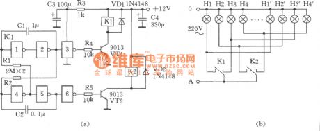
As seen in the figure is the separate-excited crossed oscillator used quad cycled colored lights controller circuit. In this circuit, the quad cycled colored lights can be controlled by only two single contact relays 4088. The operation principle is: The separated-excited crossed oscillatory circuit composed of IC1 6 NOT gate CD4069 and C1,C2,R1,R2 has a direct control over crystal triode VT1 and VT2. The driving relay K1 and K2 realise the crossed split-phase output, that is after K1 is connected, K2 will be connected, then K2 is cut off after K1 is cut off, and this process makes a circle. In this figure, (b) is the connection diagram of colored lights. (View)
View full Circuit Diagram | Comments | Reading(381)
Self-excited Multivibrator Circuit Composed of CC4093
Published:2011/4/21 21:01:00 Author:Sue | Keyword: Self-excited, Multivibrator


When the multivibrator is composed of Schmitt trigger, only a resistance and a capacitor need to be circumscribed. This circuit is designed for the low frequency oscillator with controllable oscillation and less demand on accuracy. As seen in the figure is the self-excited multivibrator composed of Schmitt trigger CC4093 with 4-2 imput. As to the waveform, see the figure below:
(View)
View full Circuit Diagram | Comments | Reading(514)
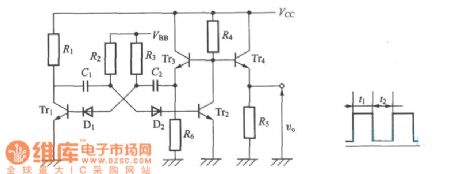
Circuit of Self-excited Multivibrator to Improve Waveform and Stability
Published:2011/4/20 21:49:00 Author:Sue | Keyword: Self-excited, Multivibrator, Waveform, Stability
View full Circuit Diagram | Comments | Reading(445)
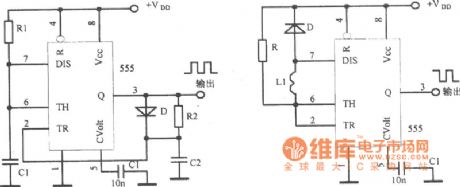
Circuit of Multivibrator Composed of Integrated Circuit 555
Published:2011/4/20 21:48:00 Author:Sue | Keyword: Multivibrator, Integrated, 555
View full Circuit Diagram | Comments | Reading(515)
PLL Pulse Generator(74HC4060、TC9122P) Circuit
Published:2011/4/21 19:56:00 Author:Sue | Keyword: PLL, Pulse, Generator, 74HC4060, TC9122P
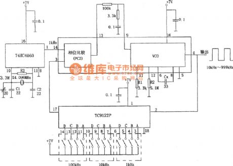
As shown in the figure is Phase-Locked Loop(PLL) pulse generating circuit. When PLL divides crystal oscillator, the 1kHz signal gained can be used as the step frequency,and there will be pulse waveforms of 10kHz 999kHz at the end of output. The 74HC4060 integrated block is an integrated chip with NOR gates and 1/2n dividing circuit inside. And the NOR gate and crystal oscillator with a frequency of 4.096MHz will constitute an oscillatory circuit, while dividing circuit gets the basic frequency signal of 1kHz by dividing it. TC9122P is a high-speed programmable counter whose dividing frequency is decided by code BCD. The program-based range of divding frequency ratio is 8-999,and this circuit works on the range of 10-999. Inside 74HC4060 there are 3 kinds of phase comparators, one of which,comarators PC2, controls the feedback by comparing the output frequency with the basic frequency. VC0's oscillator frequency is decided by Cx, R1 andR2. The minimum andmaximum frequencies are: fmin=1/R2(Cx+32pF) , fmax=1/R1(Cx+32pF) (View)
View full Circuit Diagram | Comments | Reading(5055)
| Pages:114/164 At 20101102103104105106107108109110111112113114115116117118119120Under 20 |
Circuit Categories
power supply circuit
Amplifier Circuit
Basic Circuit
LED and Light Circuit
Sensor Circuit
Signal Processing
Electrical Equipment Circuit
Control Circuit
Remote Control Circuit
A/D-D/A Converter Circuit
Audio Circuit
Measuring and Test Circuit
Communication Circuit
Computer-Related Circuit
555 Circuit
Automotive Circuit
Repairing Circuit