
Audio Circuit
Index 50
Pressure well draw off water remind circuit composed of CIC3830
Published:2011/4/26 2:41:00 Author:TaoXi | Keyword: Pressure well, draw off water, remind circuit
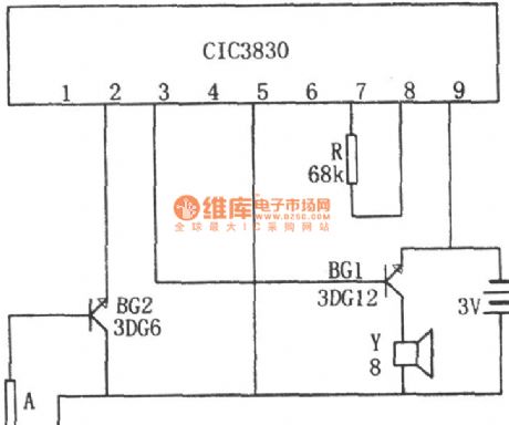
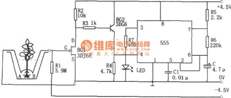
The pressure well draw off water remind circuit is as shown. This circuit is composed of the water level probe A, music IC CIC3830, and the speaker.etc.
If the water level is higher than probe A, BG2 turns on, the CIC3830 starts working, the output music signal is amplified by BG1 and then promote the sound speaker Y to remind the master to draw off water. If the water level is lower than probe A, BG2 turns off, the CIC3830 stops working to send out music signal.
If you don't draw off the water, the circuit will continue to play the music until you draw off the water, so we can avoid the well pipe damaged in the cold winter. (View)
View full Circuit Diagram | Comments | Reading(710)
Fridge close door reminding circuit
Published:2011/4/25 20:25:00 Author:TaoXi | Keyword: Refrigerator, close door reminding circuit

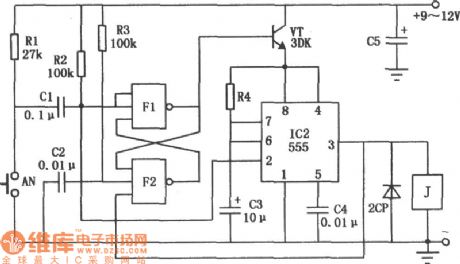
This circuit can send out the warning voice of close the door please if you open the fridge door for several seconds to remind the owner close the door in time. The circuit is as shown. The left of dotted line is fridge lighting control circuit, S1 is the fridge light door-control switch; right of dotted line is fridge's close-door warning circuit. When the fridge door opens, Sl automatically closes and the light H turns on. The DC power supplier charges the C3 by R3. Because the voltage across the capacitor can not change suddenly, so the positive electrode of C3 is still low-level current, VD6, VTl and VT2 cut-off. Value of R5, C5 determines the level of voice tones, in the figure there will be a girl's voice close the door please . If the value of C5 increased to 560pF, there will be a boy's voice close the door please . (View)
View full Circuit Diagram | Comments | Reading(758)
Rat Exterminator E-cat Circuit
Published:2011/4/25 20:28:00 Author:TaoXi | Keyword: E-cat, Rat Exterminator
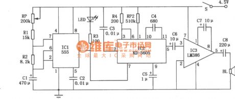
The Rat Exterminator E-cat Circuit is as shown. ICl is the time base IC NE555, the time control circuit is composed of the NE555, potentiometer RP, resistors Rl, R2 and capacitor Cl, this potentiometer controls the interval of the meows. IC2 is the mew IC KD-5605, this device save the mew. Close the switch S, power supplier charges Cl by the RP, Rl, R2, when the two ends voltage is 2/3 of the power supplier, pin-3 of ICl outputs the low-level current, LED light, at the same time IC2 works and output the meow signal, this signal is amplified by the IC3 to promote the loud speaker BL to send out the realistic meow. At the same time, discharge tube of the ICl connected to discharge power to the pin-7 of IC1. When two ends voltage of Cl drops to l/3 of power supplier, pin-3 of ICl output high-level current, LED turns off, IC2 stop working, mew stop too. The power supplier charges Cl by the RP, Rl, R2. (View)
View full Circuit Diagram | Comments | Reading(1009)
TC9465F Karaoke Single-chip LSI Circuit
Published:2011/4/25 2:49:00 Author:TaoXi | Keyword: Karaoke, Single-chip, LSI

The TC9465F is one kind of Karaoke Single-chip LSIwhich is produced by the Toshiba company, and this device is designed for the LD/CD sing stereo equipment and VTR.
1.TC9465F's block diagram and pin function
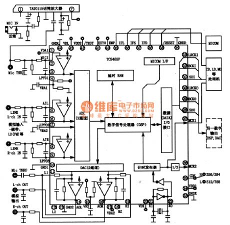
The TC9465F Manifold-circuit has three analog channels and a digital stereo input port and two simulation and output ports; the DAC using the Σ-△ modulation and oversampling mode; the built-channel ADC is the pre-filter amplifier with the 64Kbit delay RAM and the digital signal processor (DSP).etc.
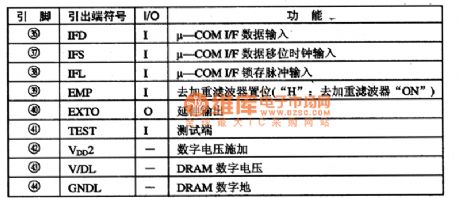
The TC9465F's inside block diagram and typical application circuit is shown as figure 1. This IC is in the 44-pin QFP package, the integrated circuit's pin functions and data are listed in Table 1.
Table 1. The Pin Functions Of The TC9465F IC
Figure 1. The TC9465F's inside block diagram and typical application circuit
2. The main electrical parameters of TC9465F
The TC9465F IC built-in ADC's total harmonic distortion is THD=-65dB, the SNR is S/N = 78dB (typical); the TC9465F's 2-channel digital to analog converter (DAC) has the third analog filter with THD=-85dB, S/N=93dB(typical).
The TC9465FR's input voltage (V(IN)) range is from -0.3V to (V(DD)+0.3) V, and the maximum power (Po) is 5mW. The operating voltage is 5±0.5V, the supply current is 48mA (typical value).
3.TC9465F typical application circuit
The TC9465 manifold's typical application circuit is shown in Figure 1. (View)
View full Circuit Diagram | Comments | Reading(2267)
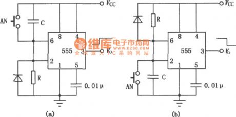
Circuit Of Flowerpot Water Alarm Composed of 555
Published:2011/4/25 19:13:00 Author:TaoXi | Keyword: Flowerpot, Water Alarm
(View)
View full Circuit Diagram | Comments | Reading(716)
Water full alarm circuit compose of 555
Published:2011/4/25 9:54:00 Author:TaoXi | Keyword: Water full alarm
The water full alarm circuit is as shown. The core of this circuit is the multivibrator which is composed of 555 and R3、R4、C1. The oscillation frequency of this multivibrator is f=1.44/(R3+2R4)C1, frequency of the corresponding parameters is about 1kHz.
When the water is full, A and B are in the short-circuit state, BG1 close and trig the oscillator start-up, pin-3 outputs the oscillation signal to drive the speaker Y, so we know the water is full.
(View)
View full Circuit Diagram | Comments | Reading(732)
Bus door-close automatic notification device (555、KD153、KD28) circuit
Published:2011/4/25 9:43:00 Author:TaoXi | Keyword: Bus, door-close, automatic notification device
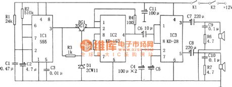
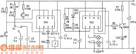
The Bus door close automatic notification device (555、KD153、KD28) circuit is as shown. This circuit is composed of monostable delay circuit, Ding-Dong IC KD-153, dual power amplifier integrated circuit KD-28 and the audio circuit (speaker).
The monostable delay circuit is composed of the IC1(555) and R1, C1, R2, C2. When the micro switch K1, K2 is closing, voltage of C1 can not change, 555 reset the place because of the pin-2 is low-level (<1/3VDD), pin-3 outputs the high-level current to conduct BG1, so the KD-153 has power to work, the Ding-Dong signal is amplified by the KD-28 and then drives two speaker to send out voice. When C2's pin-6 has the electric potential of 2/3VDD, 555 resets. The speaker stop working. This period that the speaker send out sound is the monostable circuit delay's td = 1.1R2C2. Change the charge-time constant R2C2, we can adjust the sound of the time.
(View)
View full Circuit Diagram | Comments | Reading(1486)
Dual display audio indicator circuit
Published:2011/4/25 3:39:00 Author:TaoXi | Keyword: Dual display, audio indicator

This circuit indicates the audio frequency in the dual display mode, on one hand this circuit can drive a set of LED display in line. On the other hand, the changes of audio signal control these LEDs to change the brightness by six levels, the rhythm of brightness variation is changing with the audio signal. A set of LED uses these two kinds of display modes to get for better results.
(View)
View full Circuit Diagram | Comments | Reading(1020)
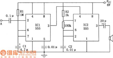
Music tone generator circuit
Published:2011/4/25 8:46:00 Author:TaoXi | Keyword: Music tone, generator

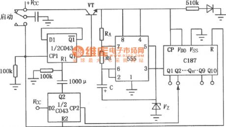
The figure of the music tone generator circuit is as shown. This circuit is composed of five pieces of time base circuit NE555 and one piece of CD4017 decade counter, and this circuit can produce 10 different tones, every tone can be set by the preset potentiometer. In addition, the circuit can produce two effect-tones.
(View)
View full Circuit Diagram | Comments | Reading(1598)
Accurate Timing Circuit Used to Adjust Capacitor Tolerance
Published:2011/4/24 21:05:00 Author:Sue | Keyword: Accurate, Timing, Capacitor Tolerance
View full Circuit Diagram | Comments | Reading(602)
Dark Room Time Controller Circuit Composed of 555
Published:2011/4/24 21:12:00 Author:Sue | Keyword: Dark Room, Time Controller, 555
View full Circuit Diagram | Comments | Reading(567)
Low Power Consumption Timer Circuit Composed of 555
Published:2011/4/24 21:15:00 Author:Sue | Keyword: Low Power Consumption, Timer, 555
View full Circuit Diagram | Comments | Reading(846)
Portable Loudspeaker Circuit
Published:2011/4/24 0:16:00 Author:TaoXi | Keyword: Portable, Loudspeaker
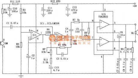
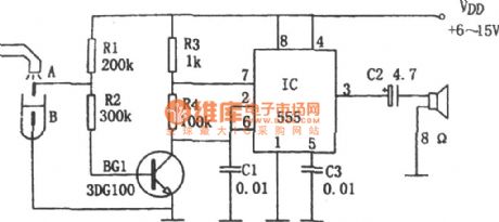
The Portable Loudspeaker Circuit is as shown. This device is composed of a dual op amp and a dual power amplifier IC, the amplifier class is BTL bridge circuit, in the same supply voltage condition, the output power is four times of circuit A. And this device is suitable for a wide supply voltage range (6V to 15V). (View)
View full Circuit Diagram | Comments | Reading(827)
Solid Recorder Circuit
Published:2011/4/24 0:34:00 Author:TaoXi | Keyword: Solid Recorder
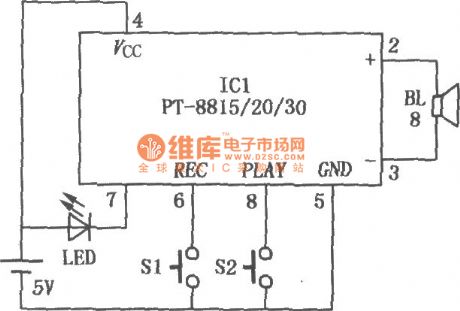
The Solid Recorder Circuit is as shown. ICl is the fool type IC of voice recording & broadcasting (PT-8815/20/30). When this device is working, we press the recording switch Sl to light the LED, this means the ICl is under the recording mode, so we can record to the speaker BL. After recording, we press the playback switch S2 to play the sound we just recorded. The circuit can be widely used in various of occasions that need voice prompt. (View)
View full Circuit Diagram | Comments | Reading(3104)
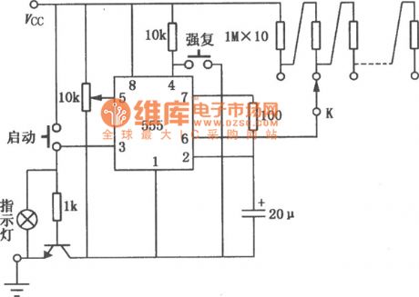
Electronic Touch Video Game Circuit Composed of 555
Published:2011/4/22 22:58:00 Author:Sue | Keyword: Electronic, Touch, Video Game, 555
View full Circuit Diagram | Comments | Reading(1603)
Long Time Delay Circuit Composed of 555
Published:2011/4/22 22:58:00 Author:Sue | Keyword: Long Time Delay, 555
View full Circuit Diagram | Comments | Reading(590)
Timing Circuit Composed of 555
Published:2011/4/22 22:57:00 Author:Sue | Keyword: Timing, 555
View full Circuit Diagram | Comments | Reading(491)
Accurate Timing Circuit Composed of 555
Published:2011/4/22 22:58:00 Author:Sue | Keyword: Accurate Timing, 555
View full Circuit Diagram | Comments | Reading(529)
Contactless Darkroom Timer Circuit Composed of 555
Published:2011/4/22 22:57:00 Author:Sue | Keyword: Contactless, Darkroom, Timer, 555
View full Circuit Diagram | Comments | Reading(787)
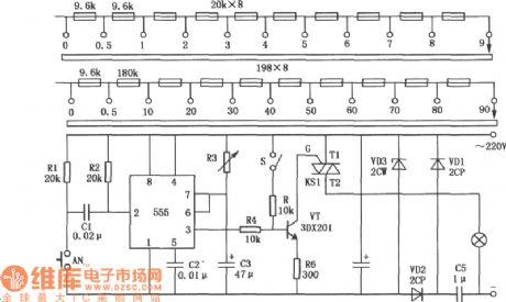
Wall S511-40 Type Electric Fan Clock Control Circuit
Published:2011/4/23 1:31:00 Author:Robert | Keyword: Electric Fan, Clock Control
Wall S511-40 Type Electric Fan Clock Control Circuit is shown below:
(View)
View full Circuit Diagram | Comments | Reading(729)
| Pages:50/54 At 204142434445464748495051525354 |
Circuit Categories
power supply circuit
Amplifier Circuit
Basic Circuit
LED and Light Circuit
Sensor Circuit
Signal Processing
Electrical Equipment Circuit
Control Circuit
Remote Control Circuit
A/D-D/A Converter Circuit
Audio Circuit
Measuring and Test Circuit
Communication Circuit
Computer-Related Circuit
555 Circuit
Automotive Circuit
Repairing Circuit