
Audio Circuit
Index 51
Four-syllable circuit
Published:2011/4/21 22:09:00 Author:Nicole | Keyword: four-syllable
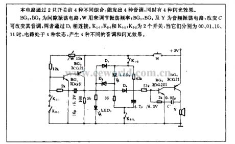
With four different groups of 2 switches, this circuit can send out 4 tones, and 4 flashing effects.
BG1, BG2 are gap oscillation circuit, W is used to adjust oscillation frequency; BG3, BG4 and Y are audio oscillation circuit, if C changes, the tone can be changed, they are connected by D3. K1-1, K2-1 and K1-2, K2-2 are two switches, when they are 00, 01, 10, 11, the circuit is in four states, and it will produce 4 kinds of tone and flashing effects. (View)
View full Circuit Diagram | Comments | Reading(661)
Circuit Of LED Digital Voice Timekeeping Clock
Published:2011/4/21 3:42:00 Author:TaoXi | Keyword: LED, Digital Voice Timekeeping
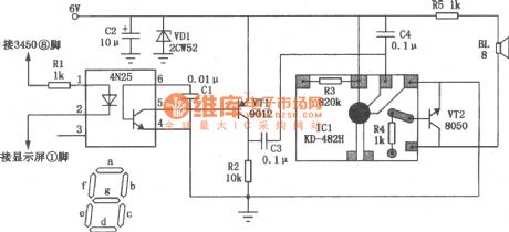
General dynamics LED digital clock does not have the timekeeping function, but we only need to add a simple circuit to make it achieve the function of whole point timekeeping. This circuit has the programmable mute function, it will not alarm from 23:00 to 5:00. So it will not affect our sweety dream. The circuit is as shown. The signal of whole point timekeeping comes from the 8-pin of LED digital clock IC 3450 or 8560, this pin is the output-b-segment of the common cathode display. When the number is 0 to 4, b-segment is high level 1 , only when the number is 5, the level is 0 . So that when the time advanced from 59 minutes to 00 minutes, the potential changes from 0 to 1. This signal is limited by the resistor Rl, the 4N25 optocoupler will isolate coupling, transistor VT1 enlarge the signal and at last speaker BL will issue the chime sound. (View)
View full Circuit Diagram | Comments | Reading(1639)
Circuit Of Electronic Megaphone
Published:2011/4/21 2:39:00 Author:TaoXi | Keyword: Electronic Megaphone
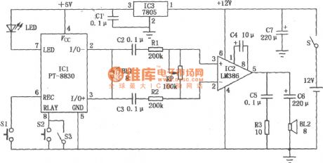
The circuit of electronic megaphone is as shown, it composed of three parts: voice recording, audio power amplifier and power supply. The ICl is the fool type of voice recording IC (PT-8815/20/30), it has the function of 30 seconds voice recording and 30 seconds playback; IC2 is the integrated power amplifier (LM386) and used to amplify the output voice signal of ICl, and IC2helps the speaker to get enough power to send out the voice; IC3 uses the 7805-type three-terminal integrated voltage stabilizer. (View)
View full Circuit Diagram | Comments | Reading(2932)
Schematic Of AN7105 Single Cassette Stereo Player
Published:2011/4/20 8:09:00 Author:TaoXi | Keyword: Single Cassette, Stereo Player, AN7105

The schematic of AN7105 Single Cassette Stereo Player is shown in the figure. (View)
View full Circuit Diagram | Comments | Reading(1966)
Circuit Of Intercom Speaker
Published:2011/4/20 21:54:00 Author:TaoXi | Keyword: Intercom Speaker
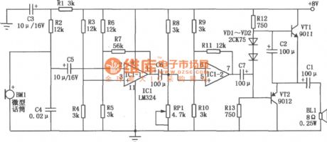
The circuit of intercom speaker in one direction is as shown (the other direction circuit is the same). The core component of the intercom speaker is the LM324 (ICl quad op amp integrated circuit), each amplifier in both directions uses two of four operational amplifiers. The microphone BM1 is one kind of high sensitivity miniature electret speaker devices, the model is 84G9, you should notice the polarity when welding. Two-stage op-amp ICl-1, ICl-2 and the external components make up the negative-feedback amplifier. R7, R11 are the negative-feedback resistor which is used to improve the stability of the circuit. Potentiometer RPl is used to fine-tuning the operating point, make the waveform symmetry, also reduce the non-linear distortion. Resistor Rl, capacitor C3 form the decoupling filter circuit to reduce the power supply hum. (View)
View full Circuit Diagram | Comments | Reading(2029)
Circuit Of CXA1034P/1034M Single Cassette Stereo Player
Published:2011/4/20 8:07:00 Author:TaoXi | Keyword: Single Cassette, Stereo Player

Left figure is the internal circuit diagram of the CXA1034P/1034M, and the right figure is the typical application circuit of it. (View)
View full Circuit Diagram | Comments | Reading(760)
Circuit Of KA22131 Single Cassette Stereo Player
Published:2011/4/20 8:07:00 Author:TaoXi | Keyword: Single Cassette, Stereo Player, KA22131

The Circuit Of KA22131 Single Cassette Stereo Player is as shown. (View)
View full Circuit Diagram | Comments | Reading(620)
Circuit Of Car Audio Speaker
Published:2011/4/20 9:05:00 Author:TaoXi | Keyword: Car Audio

The figure shows the circuit of car audio speaker. The left of dotted line is the circuit of original electric speaker, Sl means the electric speaker button switch on the steering wheel. S2 is the additional SPDT, for the switch between the original car electric horn and voice horn. When the switch S2 set to 2 , press the switch Sl, capacitor Cl is charged, transistor VTl, VT2 conducted, relay Jl picked, its normally open contact point J1-1 closed for 15 seconds to supply power to the circuit. ICl is designed as the dedicated voice circuits HL-169A, because of its working time is 2.8 seconds, so use the transistor VT3, VT4 to form the self-excited multivibrator, export a high level as a trigger signal per three seconds, this makes ICl export a voice signal per three seconds, transports into IC2 to enlarge the audio power, at last speaker BL issues the voice.
(View)
View full Circuit Diagram | Comments | Reading(642)
Circuit Of KA2213 Single Tape Recorder
Published:2011/4/20 7:21:00 Author:TaoXi | Keyword: KA2213, Single Tape, Recorder

The circuit of KA2213 single tape recorder is as shown. (View)
View full Circuit Diagram | Comments | Reading(2442)
Greenhouse or plastic house anti-condensation automatic vent with birdsong phonation circuit
Published:2011/4/20 6:43:00 Author:Nicole | Keyword: greenhouse, plastic house, automatic vent, birdsong

The circuit is as shown. It is composed of resistor type dew condensation sensor, electronic switch, relay control discharge fan circuit, birdsong phonation circuit, audio power amplifier circuit and AC depressurization rectifier circuit. RH is a resistor type dew condensation sensor, it is sensitive to the high humidity air, and it can detect whether the steam in the air will be dew condensation. (View)
View full Circuit Diagram | Comments | Reading(1071)
Greenhouse flower seedling humidity control with birdsong circuit
Published:2011/4/20 20:18:00 Author:Nicole | Keyword: greenhouse, flower seedling, birdsong

The circuit is as shown, it is composed of humidity semsor, detection circuit, temperature indicator, comparison circuit, SCR control heating circuit, birdsong phonation circuit and AC depressurization rectifier circuit. RH is humidity sensor, it adopts MS01-B, when the relative humidity changes in the range of 20%~90%, its resistance will change between few KΩ and several hundreds kΩ. (View)
View full Circuit Diagram | Comments | Reading(1031)
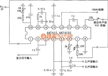
Circuit Of AN7415/7415S FM Stereo Decoder
Published:2011/4/20 8:13:00 Author:TaoXi | Keyword: FM, Stereo Decoder
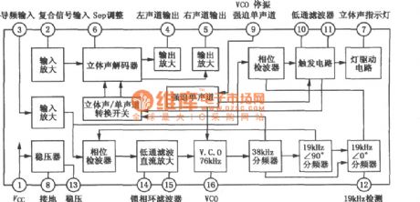
The Internal Block Diagram of The AN7415/7415S
 The Typical Application Circuit Of The AN7415/7415S (View)
View full Circuit Diagram | Comments | Reading(2545)
Circuit Of Induction Telephone Loudspeaker
Published:2011/4/20 9:36:00 Author:TaoXi | Keyword: Induction, Telephone Loudspeaker
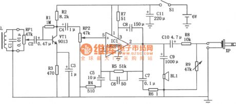
In some cases such as the telephone conference, we need to amplify the voice of telephone to lots of people, and we need to record the contents from the telephone. This circuit can simultaneously satisfy both of these requirements, do not need to make any changes, just put it near the telephone. When the voice current through the coil inside the telephone, there is a magnetic field in the vicinity, so If you put a coil L at both ends, the magnetic field will induce the signal voltage, then amplify the signal to amplify the voice of telephone to lots of people. Telephone inductive amplifier circuit is as shown, coil L will be converted the leakage magnetic field of voice into the electric signal, then controlled by potentiometer RP1 to get into the pre-formed amplifier stage that is composed by the transistor VT1, through the capacitor C4 and the potentiometer RP2 to get into the power amplifier stage to be amplified by the IC1 (audio integrated amplifier LM2896), output signal of pin IC1 promote sound speaker BL1 to make sound.
(View)
View full Circuit Diagram | Comments | Reading(1700)
Circuit Of LAG665D/665F Single Cassette Stereo Player
Published:2011/4/20 8:06:00 Author:TaoXi | Keyword: Single Cassette, Stereo
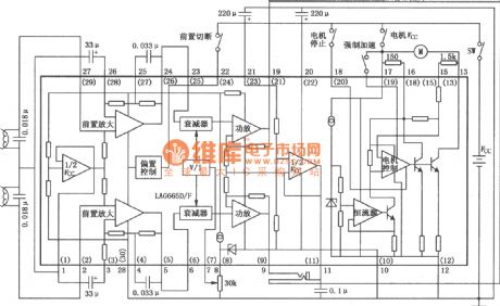
The Circuit Of LAG665D/665F Single Cassette Stereo Player is as shown. (View)
View full Circuit Diagram | Comments | Reading(732)
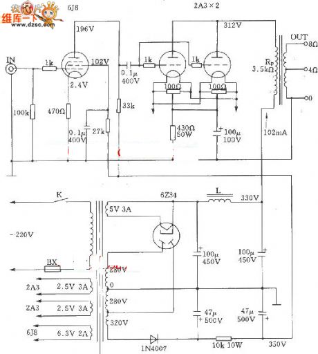
2A3 A class single-ended electron tube parallel amplifier circuit diagram
Published:2011/4/2 4:34:00 Author:Nicole | Keyword: electron tube
View full Circuit Diagram | Comments | Reading(5082)
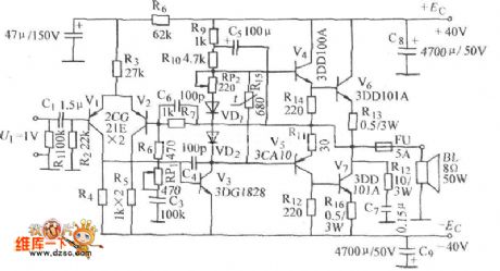
The power amplifier circuit diagram based on OCL
Published:2011/4/2 4:28:00 Author:Nicole | Keyword: power amplifier
View full Circuit Diagram | Comments | Reading(1835)
High-power electron tube single-ended A class 845 amplification circuit diagram
Published:2011/4/20 9:09:00 Author:Nicole | Keyword: electron tube

View full Circuit Diagram | Comments | Reading(2955)
Bridge exporting audio power amplification circuit diagram composed of two amplifiers in lm4752
Published:2011/4/20 9:08:00 Author:Nicole | Keyword: amplifier, audio power amplification

View full Circuit Diagram | Comments | Reading(1681)
TA7642 integrated circuit radio circuit diagram
Published:2011/4/1 3:57:00 Author:Nicole | Keyword: integrated circuit, radio

View full Circuit Diagram | Comments | Reading(7137)
Mamn C22 electron tube equalizer amplifier circuit diagram
Published:2011/4/2 4:28:00 Author:Nicole | Keyword: Mamn, electron tube, equalizer amplifier

View full Circuit Diagram | Comments | Reading(1786)
| Pages:51/54 At 204142434445464748495051525354 |
Circuit Categories
power supply circuit
Amplifier Circuit
Basic Circuit
LED and Light Circuit
Sensor Circuit
Signal Processing
Electrical Equipment Circuit
Control Circuit
Remote Control Circuit
A/D-D/A Converter Circuit
Audio Circuit
Measuring and Test Circuit
Communication Circuit
Computer-Related Circuit
555 Circuit
Automotive Circuit
Repairing Circuit