
Audio Circuit
Index 47
The precision composite buffer circuit compose of the MC1458
Published:2011/5/8 9:06:00 Author:TaoXi | Keyword: precision composite buffer

The precision composite buffer is as shown. The pre-stage of the circuit is the voltage follower that is composed of the precision op amp LM11, the parallel part of rear-stage uses the general dual op amp MC1458 (or MC1558 dual operational amplifier). The input signal adds to the same-phase input port (pin 3) of the pre-stage through R1 (10kΩ), pin 8 links the 330pF compensation capacitor C1 to achieve the over compensation, the objective is to improve the bandwidth and slew rate of the Parallel output buffer stage, sometimes we connect the 100pF capacitor C2 between the pre-stage's output port (pin 6) and the inverting input port (pin 2) to improve the stability of the circuit. Between the pre-stage's output port and the inverting input port, there are two diodes D1 and D2 (model is 1N914), the role is to clamp when LM11 is overdriven, to reduce the blocking tendency and to minimize the recovery time.
Add the 10kΩ resistor R2 between the circuit's total output port and the pre-stage LM11's inverting input port, this resistance leads the depth voltage series negative feedback to make the op amp working in linear state.
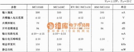
The main parameters (typical) of the dual op amp 1458 (1558):
(View)
View full Circuit Diagram | Comments | Reading(2060)
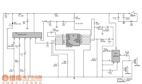
Dujiang brand 802 type radio principle circuit
Published:2011/5/8 22:07:00 Author:Christina | Keyword: Dujiang, radio, principle circuit
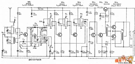
The Dujiang brand 802 type radio principle circuit is as shown:
(View)
View full Circuit Diagram | Comments | Reading(638)
General complex paralleling buffer (LF347) circuit
Published:2011/5/8 7:20:00 Author:TaoXi | Keyword: General, complex, paralleling, buffer


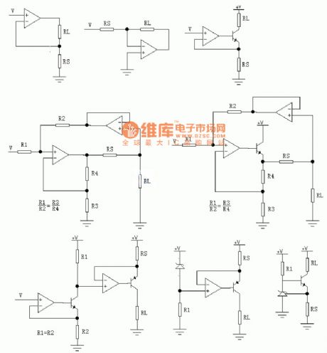
The complex paralleling buffer is composed of two or more amplifier outputs, as the figure shown. The output current of circuit is the sum of several paralleling op amps' output current. A1 and A2 can use the general integrated quad op amp LF347 (or LM324, OP496, TL35074.etc).
The main parameters of the integrated quad op amp LF347:
(View)
View full Circuit Diagram | Comments | Reading(1576)
Ring tone repeater circuit
Published:2011/5/6 2:59:00 Author:TaoXi | Keyword: Ring tone, repeater

The Ring tone repeater circuit is as shown. (View)
View full Circuit Diagram | Comments | Reading(1150)
Tone control circuit compose of the LM301AN
Published:2011/5/6 9:06:00 Author:TaoXi | Keyword: Tone control

(View)
View full Circuit Diagram | Comments | Reading(1830)
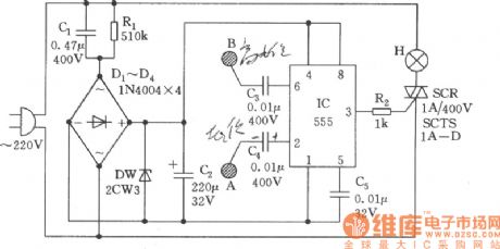
3 Light-operated Silicon-controlled Zero Passed Switch Circuit
Published:2011/5/6 7:32:00 Author:Sue | Keyword: Light-operated, Silicon-controlled, Zero Passed, Switch
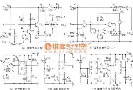
(a)Zero passed alternating current switch (1) (b)Zero passed alternating current switch (2) (c)Light-operated time-delayed switch (d)Street lamps automatic control switch (e)Corridor lamps energy saving automatic control switch (View)
View full Circuit Diagram | Comments | Reading(1240)
Logarithmic compression digital audio processor (DAC76, MN5110) circuit
Published:2011/5/6 7:47:00 Author:TaoXi | Keyword: Logarithmic compression, digital audio processor

The Logarithmic compression digital audio processor (DAC76, MN5110) circuit is as shown in the figure. (View)
View full Circuit Diagram | Comments | Reading(1488)
Touch Controlled Silicon Zero Passed Switch Circuit (1)
Published:2011/5/6 7:27:00 Author:Sue | Keyword: Touch, Controlled, Silicon, Zero Passed, Switch

(View)
View full Circuit Diagram | Comments | Reading(702)
Small active audio circuit
Published:2011/5/6 7:37:00 Author:TaoXi | Keyword: Small, active audio

The Small active audio circuit is as shown:
(View)
View full Circuit Diagram | Comments | Reading(601)
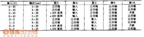
Pressure Sensor Detector Circuit
Published:2011/5/7 1:45:00 Author:Sue | Keyword: Pressure, Sensor, Detector

Nonlinearity:0.05%FSO(typical value) 3/16 pressure interface Standard ceramic substrate with temperature compensating resistance 1.5mA constant current(after amplifying can output full scare 3.00Vdc) ps.Psi=6.895kPa Pin Function: 4:+output 5:+input 6:-input 7:gain adjustment 9:gain adjustment 10:+output (View)
View full Circuit Diagram | Comments | Reading(995)
CMOS 555 Equivalent Functional Block Diagram Circuit
Published:2011/5/6 2:18:00 Author:Sue | Keyword: Equivalent, Functional Block Diagram

View full Circuit Diagram | Comments | Reading(718)
Mass V-I Converting Circuit
Published:2011/5/6 21:36:00 Author:Sue | Keyword: Mass, V-I, Converting
View full Circuit Diagram | Comments | Reading(608)
Modulation Driving Circuit
Published:2011/5/6 21:43:00 Author:Sue | Keyword: Modulation, Driving
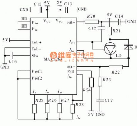
View full Circuit Diagram | Comments | Reading(674)
Simplified Radio Frequency Circuit
Published:2011/5/6 2:40:00 Author:Sue | Keyword: Simplified, Radio Frequency
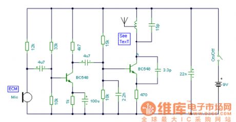
View full Circuit Diagram | Comments | Reading(758)
Precise Voltage And Current Transmitter Circuit
Published:2011/5/6 3:24:00 Author:Sue | Keyword: Precise, Voltage, Current, Transmitter
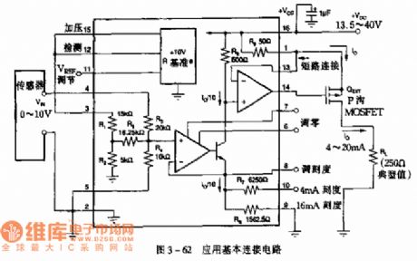
Application: It is used in pressure and temperature transmitter, industrial process control and so on.
Figure 3-62 Application Basic Junction Circuit
Basic Junction Circuit sensor inputs a voltage of 0-10V and outputs a current of 4-20mA. As seen in the figure below is the relation between variation range of input voltage, output current and pin.
(View)
View full Circuit Diagram | Comments | Reading(822)
Lamp Touch Switch Circuit
Published:2011/5/6 2:11:00 Author:Sue | Keyword: Lamp, Touch, Switch
View full Circuit Diagram | Comments | Reading(721)
Principle of Audio Circuit
Published:2011/5/6 1:09:00 Author:Sue | Keyword: Principle, Audio Circuit
View full Circuit Diagram | Comments | Reading(734)
Temperature Controlled Silicon Zero Passed Switch Circuit
Published:2011/5/6 7:31:00 Author:Sue | Keyword: Temperature, Controlled, Silicon, Zeri Passed, Switch

View full Circuit Diagram | Comments | Reading(853)
V-F Converting Circuit
Published:2011/5/6 2:47:00 Author:Sue | Keyword: V-F, Converting

Voltage/FrequencyConverting Circuit
Application: It is used inConverting Circuit with input voltage of 0-5V and output frequency of 100HZ-1MHZ.
(View)
View full Circuit Diagram | Comments | Reading(684)
Current Receiving Circuit
Published:2011/5/6 3:04:00 Author:Sue | Keyword: Current, Receiving

Application: It is used in process control, industrial control, factory automation, data acquisition and so on.
Figure 3-100 Thermocouples converting circuit (View)
View full Circuit Diagram | Comments | Reading(707)
| Pages:47/54 At 204142434445464748495051525354 |
Circuit Categories
power supply circuit
Amplifier Circuit
Basic Circuit
LED and Light Circuit
Sensor Circuit
Signal Processing
Electrical Equipment Circuit
Control Circuit
Remote Control Circuit
A/D-D/A Converter Circuit
Audio Circuit
Measuring and Test Circuit
Communication Circuit
Computer-Related Circuit
555 Circuit
Automotive Circuit
Repairing Circuit