
Index 87
DIFFERENTIAL_VERTICAL_AMPLIFIER
Published:2009/7/10 22:36:00 Author:May
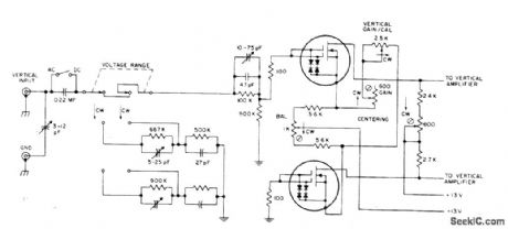
Uses two RCA 40841 dual-gate FETs invertical inputstage of solid-state oscilloscope,with gates of each connected in single-gate configuration.Circuit is designed for frequencies up to 500 MHz. Wide dynamic range permits handling of large signals、Mithout overloading.- Linear Integrated Circuits and MOS/FET's' RCA SolidState Division,Somerville,NJ,1977,p 435-436. (View)
View full Circuit Diagram | Comments | Reading(840)
ELECTROSTATIC_DEFLECTION_AMPLIFIER
Published:2009/7/10 22:35:00 Author:May
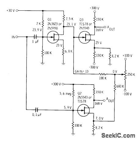
Circuit develops equal-amplitude but opposite-polarity sawtooth outputs when sawtooth input is applied to gates of Q1 and Q2. al is connected as common-source amplifier for applying opposite-polarity sawtooth to gate of Q3.Polarity at output of Q3 then becomes same as that of input, increased to amplitude suitable for deflction plates of CRT. Sawtooth at output of Q2 has opposite polarity. Circuit values are chosen to balance gain so both outputs have same magnitude.-E. M. Noll, FET Principles, Experiments, and Projects, Howard W. Sams, lndianapolis, IN, 2nd Ed., 1975, p 229-230. (View)
View full Circuit Diagram | Comments | Reading(863)
DEFLECTION_PLATE_AMPLIFIEB
Published:2009/7/10 22:34:00 Author:May
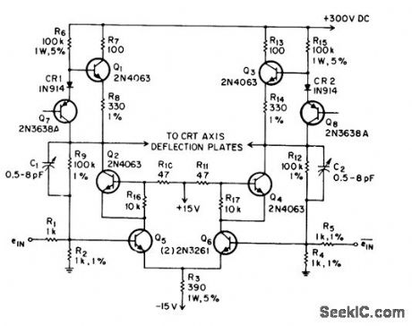
Resistive colllector network of symmetrical differentrial amplifieris replaced by constant-current source to improve slew rate of deflection amplifier driving capacitive load such as deflection plates of electrostatic cathode-ray tube.Q1 and Q2 are idetical current sources,Network Q1-CR1-Q7-R6-R8 forms current source for Q1, Q7, is used as 6.2-V zener diode,-W Peterson,Current Sources lmprove Amplifier Slew Rate,EEE Magazine, Nov,1970、p102. (View)
View full Circuit Diagram | Comments | Reading(2233)
Norton_amplifier_with_a_negative_supply
Published:2009/7/17 4:13:00 Author:Jessie
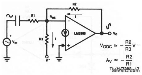
This circuit uses one section of an LM3900 to form an ac amplifier with a negative power supply. The dc biasing current, I, is established by the negative supply voltage through R3, and provides a very stable output-quiescent point for the amplifier. National Semiconductor, Linear Applications Handbook 1991 p 221 (View)
View full Circuit Diagram | Comments | Reading(576)
Norton_amplifier_with_high_input_impedance_and_high_gain
Published:2009/7/17 4:14:00 Author:Jessie
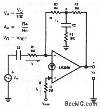
This circuit uses one section of an LM3900 to form an ac amplifier with both high input impedance (1 MΩ) and high gain (100). National Semiconductor, Linear Applications Handbook 1991 p 221. (View)
View full Circuit Diagram | Comments | Reading(613)
Norton_precision_comparator
Published:2009/7/17 4:46:00 Author:Jessie
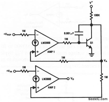
This circuit uses two sections of an LM3900 to form a precision comparator. The current established by VREF at the (-) input of amplifier 1 causes Q1 to adjust VA. The value of VA causes an equal current to flow into the (+) input of amplifier 2. This current corresponds more exactly to the reference current of amplifier 1 National Semiconductor, Linear Applications Handbook 1991 p 244. (View)
View full Circuit Diagram | Comments | Reading(652)
30_MHz_video_amplifier_using_an_MC1552G
Published:2009/7/17 4:44:00 Author:Jessie

30 MHz video amplifier using an MC1552G.Set R to 1 K for a voltage gain of 55(courtesy Motorola semiconductor Products Inc.). (View)
View full Circuit Diagram | Comments | Reading(534)
TELEPHONE_SPEAKER_AMPLIFIER
Published:2009/7/10 22:14:00 Author:May

This simple telephone amplifier (which can be switched off for privacy) allows everyone in the room to listen to your telephone conversations. (View)
View full Circuit Diagram | Comments | Reading(1984)
Norton_noninverting_low_voltage_comparator
Published:2009/7/17 4:44:00 Author:Jessie

This circuit uses one section of an LM3900 to form a noninverting comparator. The circuit can compare voltages between zero and 1V, as well as large negative voltages. When working with negative voltages, the current supplied by the common-mode network must be large enough to satisfy both the current-drain demands of the input voltages, and the bias-current requirements of the amplifier. National Semiconductor, Linear Applications Handbook 1991 p. 243 (View)
View full Circuit Diagram | Comments | Reading(713)
Wide_band_video_amplifier_using_an_ECG915_operational_amplifier_with_75_ohm_coax_drive_capability
Published:2009/7/17 4:44:00 Author:Jessie

Wide-band video amplifier using an ECG915 operational amplifier with 75-ohm coax drive capability (courtesy GTE Sylvania Incorporated). (View)
View full Circuit Diagram | Comments | Reading(639)
SUMMING_CHOPPING_AMPLIFIER
Published:2009/7/10 22:09:00 Author:May

D-c operational amplioer is connected as summing amplifier with two inputs. Input-output rela-tionship is independent of ampliier charac.teristics because amplifer gcdn is sufficienlly high and effects of d.c drift in transistor circults are sufficienlly small. D-c and low-fre-quency components are amplifier in chopper amplifier and integrating ampliler, while high-frequency a-c components go through preamplifier.The two signals are combined and further boosted by power omplifier. In togretting section has time constant of 12 sec determined by C2-R3.-W. Hochwald and F.H. Gerhard, D-C Operational Amplifier With Transistor Chopper, Electronics, 32;17, p 94-96. (View)
View full Circuit Diagram | Comments | Reading(912)
Video_switch
Published:2009/7/17 4:42:00 Author:Jessie

Video switch. With a logic one at pin 1 the amplifier is turned on (courtesy Motorola Semiconductor Products Inc.). (View)
View full Circuit Diagram | Comments | Reading(1865)
Video_amplifier_with_AGC_using_an_MC1553_wide_band_amplifier
Published:2009/7/17 4:42:00 Author:Jessie


Video amplifier with AGC using an MC1553 wide-band amplifier (courtesy Motorola Semiconductor Products Inc.). (View)
View full Circuit Diagram | Comments | Reading(680)
Video_amplifier_with_AGC_using_an_MC1552_1553_wide_band_amplifier
Published:2009/7/17 4:41:00 Author:Jessie

Video amplifier with AGC using an MC1552/1553 wide-band amplifier (courtesy Motorola Semiconductor Products Inc.). (View)
View full Circuit Diagram | Comments | Reading(575)
ELECTROSTATIC_DEFLECTIO_AMPLIFIER
Published:2009/7/10 22:03:00 Author:May

Combines frequency response of cascode am pilfer with linearity of long-tailed pair fed by constant current, Adjust R for 3 mA through each load resistor. Output transistors require small heatsinks.-G. A Johnston, Deflection Amplifier, Wireless World, Nov. 1973, p 560. (View)
View full Circuit Diagram | Comments | Reading(1209)
Norton_AND_gate_and_NAND_gate_with_high_fan_in
Published:2009/7/17 4:41:00 Author:Jessie


This circuit uses one section of an LM3900 to form a multiple-input AND gate, with an input-diode network that is similar to that of DTL. Interchange the inputs to form a NAND gate. National Semiconductor, Linear Applications Handbook 1991 p 240 (View)
View full Circuit Diagram | Comments | Reading(583)
HYBRID_D_C_OPERATIONAL_AMPLIFIER
Published:2009/7/10 22:02:00 Author:May

Uses Goldberg chopper-stabilized principle for d-c drift correction. D-c gain is 900,000, input impedance 230,000 ohms, and output impedance 1,000 ohms. Generates -20 to +20v.across 10,000-ohm load at 0 to 800 cps.-R. L.Konigsberg, Designing Hybrid D.C Amplifiers to Withstand Missile Environments, Electronics,34:32, p157-159. (View)
View full Circuit Diagram | Comments | Reading(537)
Video_amplifier_with_AGC_using_an_MC1552
Published:2009/7/17 4:39:00 Author:Jessie

Video amplifier with AGC using an MC1552(courtesy Motorola semiconductor Products Inc.). (View)
View full Circuit Diagram | Comments | Reading(547)
Video_amplifier_using_an_MC1590
Published:2009/7/17 4:39:00 Author:Jessie

Video amplifier using an MC1590(courtesy Motorola Semiconductor Products Inc.). (View)
View full Circuit Diagram | Comments | Reading(561)
Norton_AND_gate_and_NAND_gate_with_high_fan_out
Published:2009/7/17 4:38:00 Author:Jessie

This circuit uses one section of an LM3900 to form a three-input AND gate with a fan out of 50. One of the 24-kΩ resistors and R2 can be omitted to form a two-input AND gate. Interchange the inputs to form a NAND gate. National semiconductor, Linear Applications Handbook 1991 p 240. (View)
View full Circuit Diagram | Comments | Reading(573)
| Pages:87/250 At 2081828384858687888990919293949596979899100Under 20 |
Circuit Categories
power supply circuit
Amplifier Circuit
Basic Circuit
LED and Light Circuit
Sensor Circuit
Signal Processing
Electrical Equipment Circuit
Control Circuit
Remote Control Circuit
A/D-D/A Converter Circuit
Audio Circuit
Measuring and Test Circuit
Communication Circuit
Computer-Related Circuit
555 Circuit
Automotive Circuit
Repairing Circuit