
555 Circuit
Index 40
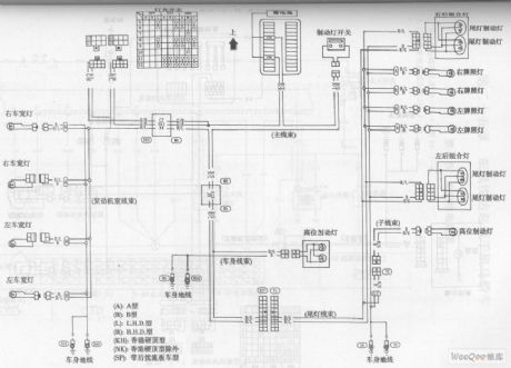
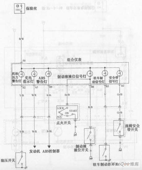
The No.1 Warning Lamp Circuit of the Bluebird Car
Published:2011/5/9 2:28:00 Author:Borg | Keyword: Warning Lamp, Bluebird
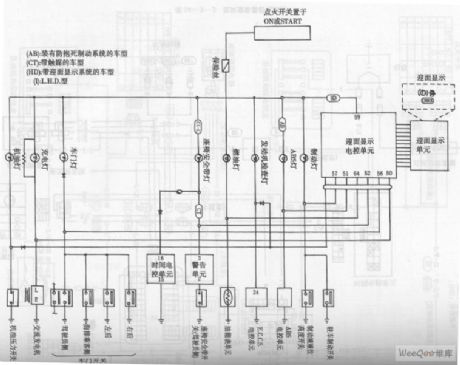
(AB):the model withAnti-lock Brake Systems (CT): the model with catalysts (HD):the model with head-on display system (I): the L.H.D type
The No.1 Warning Lamp Circuit of the Bluebird Car (View)
View full Circuit Diagram | Comments | Reading(587)
The No.2 Warning Lamp Circuit of the Bluebird Car
Published:2011/5/9 0:05:00 Author:Borg
The No.2 Warning Lamp Circuit of the Bluebird Car (View)
View full Circuit Diagram | Comments | Reading(607)
Mitsubishi Pajero (PAJERO) light off-road vehicle powered car window theory circuit diagram
Published:2011/5/8 11:41:00 Author:Rebekka | Keyword: Mitsubishi Pajero , light off-road vehicle powered car
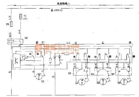
Mitsubishi Pajero (PAJERO) light off-road vehicle powered car window theory circuit diagram
50 door motor relay; 51 window motor for a main switch; 52,54,56,58 left, right, left rear, right front window motor; 53,55,57 right, left rear, right front window motor Vice switch; 68 bit big switch.
Mitsubishi Pajero (PAJERO) light off-road vehicle powered car window theory circuit diagram.
(View)
View full Circuit Diagram | Comments | Reading(1287)
The Headlights Circuit of the Bluebird Car
Published:2011/5/8 9:46:00 Author:Borg | Keyword: Headlights, Bluebird
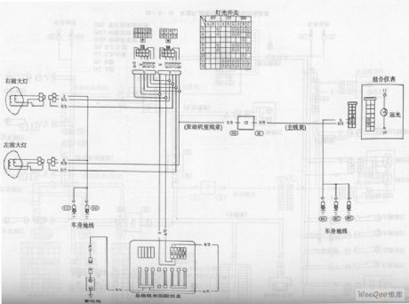
The Headlights Circuit of the Bluebird Car (View)
View full Circuit Diagram | Comments | Reading(597)
The Circuit of License Plate Lamps,Tail Lamps and Brake Lamps of the Bluebird Car
Published:2011/5/8 10:02:00 Author:Borg | Keyword: License Plate Lamps, Tail Lamps , Brake Lamps, Bluebird
(A):Type A (B):Type B (C):Type L.H.D (D)Type R.H.D (KH):the type of Hongkong hardtop (NK):except the type of Hongkong hardtop (SP):the model with rear spoilers
The Circuit of License Plate Lamps,Tail Lamps and Brake Lamps of the Bluebird Car (View)
View full Circuit Diagram | Comments | Reading(715)
Light Control Street Lamp Circuit Using ne555
Published:2011/5/5 20:25:00 Author:Robert | Keyword: Light Control, Street Lamp

As shown this circuit is specially designed. The light control switch and the electrical networks are connected by the two-wire connected method. It can replace the general switch directly to make the normal lamps be the light control automatic street lamps.
(View)
View full Circuit Diagram | Comments | Reading(2968)
Using NE555 Skillfully as High and Low Frequency Signal Tracer Circuit
Published:2011/5/5 2:57:00 Author:Joyce | Keyword: Using NE555 Skillfully as, High and Low Frequency, Signal, Tracer
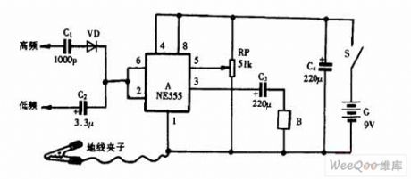
Using NE555 Skillfully as High and Low Frequency Signal Tracer Circuit (View)
View full Circuit Diagram | Comments | Reading(3275)
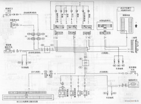
Beijing Cherokee 4.0L engine electronic control system sensor and computer wiring diagram
Published:2011/5/5 6:31:00 Author:Rebekka | Keyword: Beijing Cherokee 4.0L engine, electronic control system sensor , computer wiring
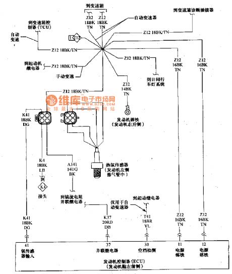
Beijing Cherokee 4.0L engine electronic control system sensor and computer wiring diagram. (View)
View full Circuit Diagram | Comments | Reading(983)
555 Electronic flute circuit
Published:2011/5/4 21:03:00 Author:Ecco | Keyword: 555, Electronic flute
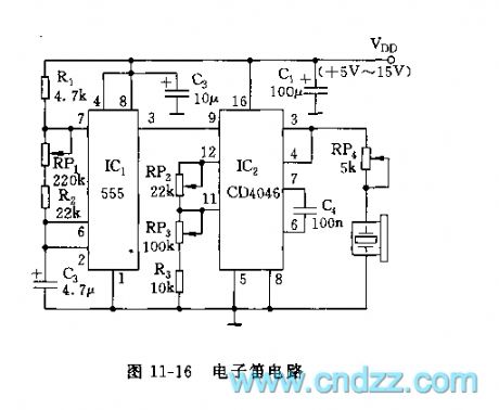
The circuit shown in Figure 11-16 includes the timer and voltage-controlled oscillator. IC1 (555) and R1, RP1, R2, C2 form astable multivibrator, f = 1.44 / (R1 + RP1 +2 R2) C2, the oscillation frequency and duty cycle can be changed by adjusting RP1. IC2 (CD4046) is the CMOS-type phase-locked loop (PLL), the center frequency of voltage-controlled oscillation depends on the external components, sucn as C4, RP2, RP3, R3. The center frequency fmin = 1 / (RP3 + R3) C4, fmax = 1 / (RP2 + RP3 + R3) C4.
Adjusting RP2, RP3 can change the two tones of the electronic flute, adjusting RP1 can change the changing rate of two tones.
(View)
View full Circuit Diagram | Comments | Reading(2142)
555 Simple Linear Sawtooth Wave Generator Circuit
Published:2011/5/3 6:04:00 Author:Robert | Keyword: Linear Sawtooth Wave, Generator

As shown, after 555 triggering andfliping,the capacitor C generates the sawtooth waveby charging,and this wavecan be the scanningvoltage of the oscilloscope, but its linearity is not very well, so this circuit uses the constant current source instead of the timing resistor during themonostable and transient time, this can get the linear sawtooth wave. The linear ramp-up time is shown below.
(View)
View full Circuit Diagram | Comments | Reading(1922)
555 Square Wave And Sawtooth Wave Generator Circuit
Published:2011/5/3 7:15:00 Author:Robert | Keyword: Square Wave, Sawtooth Wave, Generator
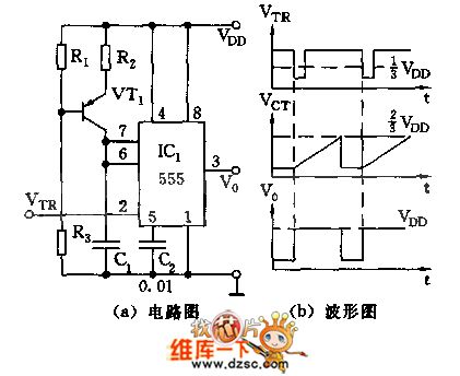
As shown, 555 and R2, C1, VT1 etc. make up a monostable trigger circuit, the difference from the general trigger is thatVT1,R1,R2,R3 make up a constant current source, to charge to C1 with constant current, whichmakes C1's charging voltage linearity good and has precise delay. The delay time td≈1.1R2C1. It is required the trigger pulse cycle time T>td. The output wave is shown as picture below. (a) is circuit. (b) is wave.
(View)
View full Circuit Diagram | Comments | Reading(1547)
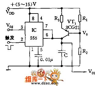
555 Zero-Symmetric Bi-Directional Pulse Generator Circuit
Published:2011/5/1 10:01:00 Author:Robert | Keyword: Zero-Symmetric, Bi-Directional, Pulse Generator

As shown, this circuit can meet the requirements of the periodic pulse outputing symmetrically to the ground.Under the power voltage of +/-15V, it can output +/-11V bi-directional pulse.
VT1, VT2 and R1~R4 make up the voltage shifting networks, using the floating power supply method to the IC 555. 555 and R5, R6, C2 make up the astable multivibrator, oscillation frequency is f=1.44/(R5+2*R6)C2 and it is about 90Hz.
(View)
View full Circuit Diagram | Comments | Reading(1480)
Changan Star multifunction vehicle front wiper and jet washing device circuit diagram
Published:2011/4/28 9:23:00 Author:Rebekka | Keyword: Changan Star, multifunction vehicle , front wiper , jet washing device

Changan Star multifunction vehicle front wiper and jet washing device circuit diagram is shown as above. (View)
View full Circuit Diagram | Comments | Reading(562)
Changan Star multi-purpose vehicle combination instrument circuit diagram 3
Published:2011/4/28 1:07:00 Author:Rebekka | Keyword: Changan Star, multi-purpose vehicle, combination instrument
Changan Star multi-purpose vehicle combination instrument circuit diagram is shown as above. (View)
View full Circuit Diagram | Comments | Reading(582)
Changan Star multi-purpose car electric door and window circuit diagram
Published:2011/4/28 1:06:00 Author:Rebekka | Keyword: Changan Star , multi-purpose car, electric door and window
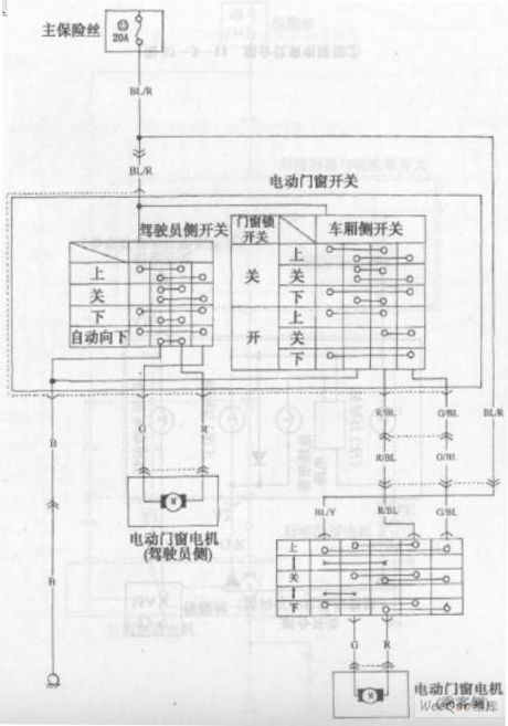
Changan Star multi-purpose car electric door and window circuit diagramis shown as above. (View)
View full Circuit Diagram | Comments | Reading(732)
Changan Star multi-purpose vehicle combination instrument circuit diagram 2
Published:2011/4/28 1:04:00 Author:Rebekka | Keyword: Changan Star , multi-purpose vehicle , combination instrument

Changan Star multi-purpose vehicle combination instrument circuit diagram is shown as above. (View)
View full Circuit Diagram | Comments | Reading(585)
Changan Star multi-purpose vehicle combination instrument circuit diagram 1
Published:2011/4/28 1:04:00 Author:Rebekka | Keyword: Changan Star , multi-purpose vehicle , combination instrument

Changan Star multi-purpose vehicle combination instrument circuit diagram is shown as above. (View)
View full Circuit Diagram | Comments | Reading(583)
555 Digital temperature sensor header circuit
Published:2011/4/27 4:26:00 Author:Ecco | Keyword: 555 , Digital, temperature, sensor header

As shown in Figure 7-33, the sensor header consists of two 1N914 diodes and a multivibrator composed of 555 and other components. Diode D is used as a part of discharging loop of 555 oscillator, the oscillation frequency changes proportionally with temperature and the impedance of the diode. The oscillation pulse output by 555 and then sent to the frequency counter to count, to reflect the changes of temperature.
(View)
View full Circuit Diagram | Comments | Reading(1633)
555 Audio ohmmeter circuit
Published:2011/4/27 4:16:00 Author:Ecco | Keyword: 555 , Audio , ohmmeter

As shown in Figure 7-9, audio ohmmeter uses 555 as the core. The circuit is actually a multivibrator. The table pen is connected to resistor Rx, and then connected to R3 in parallel, the resistance is different, the oscillation frequency is different, the level of speaker sound is also different. The resistance of measured resistor can be estimated by the level of sound.
(View)
View full Circuit Diagram | Comments | Reading(1352)
555 Negative voltage source circuit
Published:2011/4/27 3:47:00 Author:Ecco | Keyword: 555 , Negative, voltage source
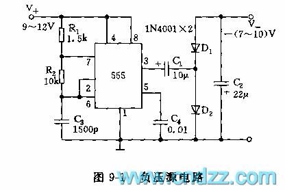
As shown in Figure 9-1, 555 and R1, R2, C3 form an astable multivibrator, f = 1.44 / (R1 +2 R2) C3, the frequency of the icon parameter is about 80kHz. R2 is greater than the R1, so the duty cycle closes to 50%. The output oscillation pulses is rectified by the D1, D2, C2, and it gets a negative voltage and offers tens of mA load current.
(View)
View full Circuit Diagram | Comments | Reading(1898)
| Pages:40/47 At 202122232425262728293031323334353637383940Under 20 |
Circuit Categories
power supply circuit
Amplifier Circuit
Basic Circuit
LED and Light Circuit
Sensor Circuit
Signal Processing
Electrical Equipment Circuit
Control Circuit
Remote Control Circuit
A/D-D/A Converter Circuit
Audio Circuit
Measuring and Test Circuit
Communication Circuit
Computer-Related Circuit
555 Circuit
Automotive Circuit
Repairing Circuit