
555 Circuit
Index 32
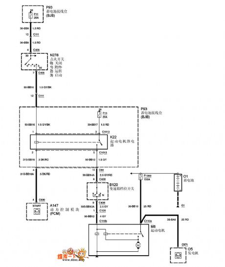
Mazda 95TAURUS (3.8L) starting circuit
Published:2011/6/21 0:39:00 Author:John
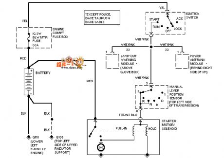
Mazda 95TAURUS (3.8L) starting circuit is shown.
(View)
View full Circuit Diagram | Comments | Reading(578)
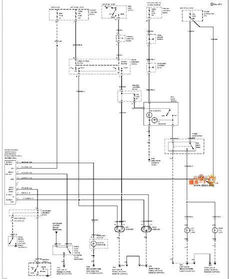
Mazda 95TAURUS (without DRL) headlights and fog lights circuit
Published:2011/6/21 0:39:00 Author:John | Keyword: headlight, fog light
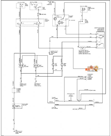
Mazda 95TAURUS (without DRL) headlights and fog lights circuitis shown. (View)
View full Circuit Diagram | Comments | Reading(691)
High-pass filter circuit
Published:2011/6/20 5:57:00 Author:John | Keyword: High-pass filter
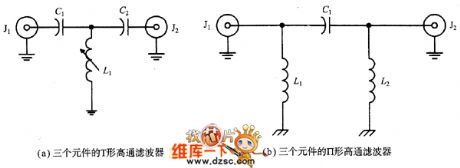
High-pass filter (HPF) cuts off signal frequency which is below -3dB cutoff frequency and allows for signal frequency which is above the cutoff frequency.
Figure (a) and Figure (b) show single high-pass filters. These are inversions of LPF single low-pass filters. Capacitance is placed in series in the signal path but the inductance is placed in parallel in the signal channel. The model shown in the figure (a) is T-shaped structure that shown in the figure (b) is Ⅱtype filter.
(View)
View full Circuit Diagram | Comments | Reading(639)
Mazda 94THUNDERBIRD airbag circuit
Published:2011/6/21 0:28:00 Author:John | Keyword: airbag

Mazda 94THUNDERBIRD airbag circuit is shown.
(View)
View full Circuit Diagram | Comments | Reading(578)
Mazda 94THUNDERBIRD electric antenna circuit
Published:2011/6/21 0:28:00 Author:John | Keyword: electric antenna
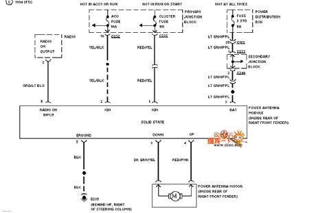
Mazda 94THUNDERBIRD electric antenna circuit is shown.
(View)
View full Circuit Diagram | Comments | Reading(606)
varactor diode adjusting MOSFET active preselector circuit
Published:2011/6/21 0:27:00 Author:John | Keyword: varactor diode, MOSFET active preselector

Varactor diode adjusting MOSFET active preselector circuit is shown.
(View)
View full Circuit Diagram | Comments | Reading(2244)
Changhe-BeiDouXing airbags and front suspension circuit
Published:2011/6/23 2:07:00 Author:qqtang | Keyword: airbags, front suspension
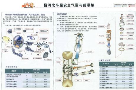
The Changhe-BeiDouXing airbags and front suspension circuitis shown in the figure.
(View)
View full Circuit Diagram | Comments | Reading(720)
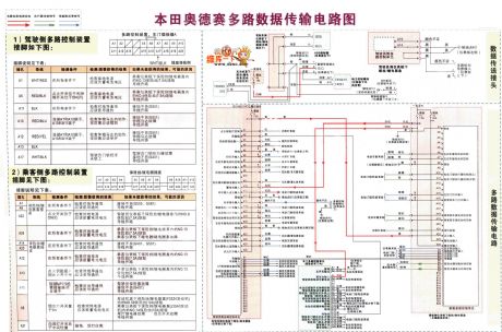
The Honda-Odyssey multi-line data transmission circuit
Published:2011/6/22 6:58:00 Author:qqtang | Keyword: Honda-Odyssey, multi-line, data transmission
View full Circuit Diagram | Comments | Reading(1299)
The YN 5203 typical application circuit
Published:2011/6/21 1:40:00 Author:Seven | Keyword: typical application circuit
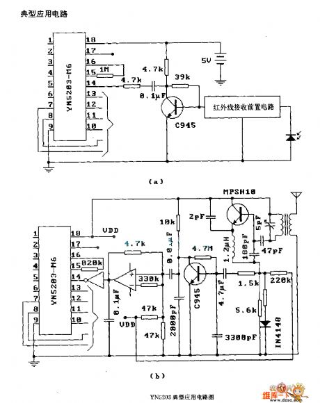
The YN 5203 typical application circuit (View)
View full Circuit Diagram | Comments | Reading(713)
Mazda 94THUNDERBIRD (with DRL) headlamp and fog lamp circuit
Published:2011/6/17 11:05:00 Author:John | Keyword: headlamp, fog lamp
Mazda 94THUNDERBIRD (with DRL) headlamp and fog lamp circuit is shown below.
(View)
View full Circuit Diagram | Comments | Reading(559)
Ford Focus automatic gear-box circuit
Published:2011/6/11 1:38:00 Author:chopper | Keyword: Ford Focus, automatic, gear-box
View full Circuit Diagram | Comments | Reading(674)
The voltage source circuit of 555 drive neon bulb
Published:2011/5/27 2:52:00 Author:nelly | Keyword: drive neon bulb, voltage source
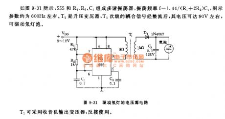
As shown in the figure 9-30,555 and R1, R2, C1 make up the astable multivibrator.The vibrational frequency: f=1.44/(R1+2R2)C1, the parameter on the figure is about 600Hz. T1 is a step-up transformer, its voltage can reach 90V and drive the neon bulb after Secondary Coupling Signal to be rectified. T1 can adopt a radio output transformer.
(View)
View full Circuit Diagram | Comments | Reading(931)
LED display driven by 74HC164 circuit (common cathode)
Published:2011/6/7 10:13:00 Author:John | Keyword: LED
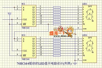
LED display 74HC164 driver circuit is shown in the following.
(View)
View full Circuit Diagram | Comments | Reading(2641)
LED driven by eight 74HC595 circuit
Published:2011/6/8 9:37:00 Author:John | Keyword: LED
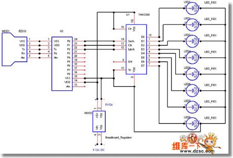
LED driven by eight 74HC595 circuits areshown in the following.
(View)
View full Circuit Diagram | Comments | Reading(6348)
Optical shaft encoder photodiode circuit
Published:2011/6/9 21:18:00 Author:John | Keyword: Optical shaft encoder, photodiode
Light emitted from incandescent light bulb reaches the photodiode through the lens, cylindrical lens and the slot of chrome optical encoding disk. Coding plate engraves according to cyclic binary code. If it is corresponded to n-bit binary code, n photodiodes should be ranked in the optical narrow line behind the slot. 16-bit requires the width of optical slit of 20μm, so the good reliability can be ensured. Microampere meter reads about 0.1μA when there exists light. And it reads about 6~10μA when there is no light. 3DG5DX2 is the composite pipe, which has a rather greater magnification and emitter output. Two pieces of 3DK2 composite Schmitt trigger, whose function is to coin. When there exists light, the output is less than 0.5V. When there is no light, the output reaches +6V.
(View)
View full Circuit Diagram | Comments | Reading(1040)
The protection circuit of 555 fridge
Published:2011/6/7 4:13:00 Author:Borg | Keyword: protection circuit
See as Figure 13-8, the protector is formed by sub-circuits of the step-down rectifier, delay starter, over/low voltage sample and trigger,etc. The protector has functions of over voltage (>245v) and low voltage(<175v) protection, off-delay operation(about 7 minutes) and so on, and it's power saving(<2w) and cost saving.
Figure 13-8. Theexternalprotection circuit of fridges
IC(555), R4 and C3 consist the single steady delay circuit, the delaying time is td=1.1R4C3, the delaying time of the parameter in the figure is about 7min. When the circuit is protecting the fridge, LED1(red) is glowing, and the fridge outlet is cut off; when it is working normally, LED2(green) is glowing.
(View)
View full Circuit Diagram | Comments | Reading(564)
The reminder circuit of opening door too long of 555 fridge
Published:2011/6/7 4:15:00 Author:Borg | Keyword: reminder circuit, 555 fridge

The reminder circuit is shown in Figure 13-23. It is a 555 timing circuit which fulfills two functions of time delay and oscillation, and it is simple and useful. With the use of 4-lead reset terminal linking to the ground connection capacitor C4, and the switching of relay connector K1-1, it can fulfill the function of time delay.
Figure 13-23 The reminder circuit of opening door too long of fridges
555,R2,R3 and C4 consist an audio oscillator which delays time for 15s. SA in the figure is the door control(light) switch of the former fridge. When the fridge door is open, SA will automatically close and the control circuit will get the power. (View)
View full Circuit Diagram | Comments | Reading(677)
555 temperature limit controller circuit with heating acoustics alarming
Published:2011/6/3 9:03:00 Author:nelly | Keyword: temperature limit controller, heating acoustics alarming

This temperature limit control circuit is made of hypotension rectifier, voltage-stabilizing circuit, temperature measurement comparator, heater and acoustics alarming circuit. It is mainly used in occasion which need higher controlled temperature, such asfluid infusion, blood transfusion heating control, incubator and so on. Its circuit is shown in the figure 12-41.
The process of temperature control is shown: when the ambient temperature is lower than the limited temperature, the resistance value of thermal resistor RT is greater, the output of comparator IC1-a is high level, the output of follower IC1-b is high level too, VT1, VT2 are turned on, the heater obtains electricity and is heated; at the same time, the heating indicator light LED1 turns on. When the ambient temperature is higher than the limited temperature, the resistance value of RT is decreased, IC1-a outputs low level, IC1-b outputs low level too, then the constant temperature indicator light LED2 turns on, at the same time, VT1, VT2 cut off, the heating is stopped.
(View)
View full Circuit Diagram | Comments | Reading(951)
555 20-way answering device circuit
Published:2011/6/7 0:37:00 Author:nelly | Keyword: answering device

As shown in the figure 11-30, the answering device circuit contains 20-way answering device switch and relevant relay control circuit, combined display digital board, audio circuit and timing circuit. After the host bringing up the question, the responder hears the sound of answering device, then he can press the answering switch, the digital dispaly board shows the answering group number. Both the positive and negative of dispaly board will dispaly, the side which is face to the responder and audience is composed of nine branches of 6.3V/0.15A bulbs( 1 word is shown by two branches); the side which is face to the host is made of LED. Each LED is in series with a 300Ω resistor, it is used to limit current. For example, the 13 group presses AN13 first, then D13, D23 turn on,J3, J 10, J11 pull in, the current passes through the paragraphes of a, b, c, d, g, h, the bulb turns on, it displays word 13 . Due to J3 pulls in, the answering power supply is cut off.
(View)
View full Circuit Diagram | Comments | Reading(590)
555 simple toy electronic organ circuit
Published:2011/6/3 19:51:00 Author:nelly | Keyword: toy electronic organ

This multivibrator circuit is composed as the core of 555 time base circuit, the tone and musical note is changed by changing the on/off of the two groups of piano keyboard switch. The circuit is shown in the figure 11-37.
The actable multivibrator is made of 555 and R1~R8, R9, C1, the different pronouncing frequency can be changed by changing the resistance of charge resistance, then it will emit different musical note. After R1~R8 are connected in series, the max resistance is 100kΩ, the basic frequency of graphical parameters are between 390~6420Hz, they are decided by A group's K1~K7 piano keyboard switch. When it is debugging, AN1, AN2 are off, a 100kΩ exponential type potentiometer is used to take down the resistance when the tone is 1, 2, 3...7, then relevent resistor is selected to connect into the circuit.
(View)
View full Circuit Diagram | Comments | Reading(2139)
| Pages:32/47 At 202122232425262728293031323334353637383940Under 20 |
Circuit Categories
power supply circuit
Amplifier Circuit
Basic Circuit
LED and Light Circuit
Sensor Circuit
Signal Processing
Electrical Equipment Circuit
Control Circuit
Remote Control Circuit
A/D-D/A Converter Circuit
Audio Circuit
Measuring and Test Circuit
Communication Circuit
Computer-Related Circuit
555 Circuit
Automotive Circuit
Repairing Circuit