555 Circuit
555 Electronic flute circuit
Published:2011/5/4 21:03:00 Author:Ecco | Keyword: 555, Electronic flute | From:SeekIC

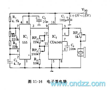
The circuit shown in Figure 11-16 includes the timer and voltage-controlled oscillator. IC1 (555) and R1, RP1, R2, C2 form astable multivibrator, f = 1.44 / (R1 + RP1 +2 R2) C2, the oscillation frequency and duty cycle can be changed by adjusting RP1. IC2 (CD4046) is the CMOS-type phase-locked loop (PLL), the center frequency of voltage-controlled oscillation depends on the external components, sucn as C4, RP2, RP3, R3. The center frequency fmin = 1 / (RP3 + R3) C4, fmax = 1 / (RP2 + RP3 + R3) C4.
Adjusting RP2, RP3 can change the two tones of the electronic flute, adjusting RP1 can change the changing rate of two tones.
Reprinted Url Of This Article:
http://www.seekic.com/circuit_diagram/555_Circuit/555_Electronic_flute_circuit.html
Print this Page | Comments | Reading(3)

Article Categories
power supply circuit
Amplifier Circuit
Basic Circuit
LED and Light Circuit
Sensor Circuit
Signal Processing
Electrical Equipment Circuit
Control Circuit
Remote Control Circuit
A/D-D/A Converter Circuit
Audio Circuit
Measuring and Test Circuit
Communication Circuit
Computer-Related Circuit
555 Circuit
Automotive Circuit
Repairing Circuit
Code: