TUA6100B6

Features: · Low impedance gain controlled RF input· Dual matched double balanced mixer· Digital generation of 00/900 LO signal· Direct down conversion from 1. IF (LNB output) to base band 0-30 MHz· IF filter not necessary· I / O for external baseband filter· CMOS PLL-Synthesizer· Active loop filte...

product image

TUA6100B6 Picture
SeekIC No. : 004533811 Detail

TUA6100B6: Features: · Low impedance gain controlled RF input· Dual matched double balanced mixer· Digital generation of 00/900 LO signal· Direct down conversion from 1. IF (LNB output) to base band 0-30 MHz· ...

floor Price/Ceiling Price

Part Number:
TUA6100B6
Supply Ability:
5000

Price Break

  • Qty
  • 1~5000
  • Unit Price
  • Negotiable
  • Processing time
  • 15 Days
Total Cost: $ 0.00

SeekIC Buyer Protection PLUS - newly updated for 2013!

  • Escrow Protection.
  • Guaranteed refunds.
  • Secure payments.
  • Learn more >>

Month Sales

268 Transactions

Rating

evaluate  (4.8 stars)

Upload time: 2025/1/11

Payment Methods

All payment methods are secure and covered by SeekIC Buyer Protection PLUS.

Notice: When you place an order, your payment is made to SeekIC and not to your seller. SeekIC only pays the seller after confirming you have received your order. We will also never share your payment details with your seller.
Product Details

Description


Features:

· Low impedance gain controlled RF input
· Dual matched double balanced mixer
· Digital generation of 00/900 LO signal
· Direct down conversion from 1. IF (LNB output) to base band 0-30 MHz
· IF filter not necessary
· I / O for external baseband filter
· CMOS PLL-Synthesizer
· Active loop filter (high voltage)
· 3 high current switch outputs
· Buffered crystal oscillator output
· Low noise reference voltage
· 3-wire bus and
· I2C bus with 4 addresses + subaddresses
· Splitting of Sat tuning range into 2/3 bands
· LO - frequency below and above input frequency possible


Application

· DBS, DVB-S, DSS Set-Top Boxes,
· any I/Q Downconverter from 950 MHz - 2150 MHz to frequencies 0 - 30 MHz


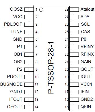
Pinout

  Connection Diagram


Specifications

Parameter Symbol
Limit Values
Units
min. max. V
Supply voltage VVCC - 0.3 5.5 V
Supply voltage 1 VVCC1 - 0.3 5.5 V
Crystal oscillator VQOSZ VVCC-3 > 0 VVCC-1 > 0 V
Crystal oscillator buffered output VXTALOUT 0 VVCC V
Synthesizer Charge pump out Loop filter in VPDLOOP 0 VVCC V
Synthesizer Loop filter tuning output VTUNE -0.3 35 V
VCO inputs VOB1,VOB2 0 VVCC V
Port outputs VP0,P1,P2 0 VVCC V
IP0,P1,P2   15 mA
IP0,P1,P2   30 mA
Port outputs , VP0,P1,P2= VVCC, I=max t Imax   1 mS
GHz-PLL Charge pump out VPDOUT 0 VVCC V
Baseband outputs I / Q VIOUT ,QOUT 0 VVCC1 V
IIOUT , QOUT   4 mA
Baseband filtered inputs I / Q VIFIN,VQFIN 0 VVCC1 V
Baseband filtered Output I / Q VIFOUT,QFOUT 0 VVCC1 V
IIFOUT,QFOUT   4 mA
AGC voltage VAGC 0 VVCC1 V
RF input VRFINX,RFINY 0 1.5 < VVCC1 V
I2C / 3-Wire-Bus SCL, SDA,CAS
BUSMODE

- 0.3
VVCC+0.3 V

All values are referred to ground (pin), unless stated otherwise.All currents are designated according to the source and sink principle, i.e. if the device pin is to be regarded as a sink (the current flows into the stated pin to internal ground), it has a negative sign,and if it is a source (the current flows from Vs across the designated pin), it has a positive sign.


Description

The TUA6100B6 is a low cost chip in the newest Infineon high speed BICMOS technology B6HFC. It is designed to implement the direct conversion receiver principle for digital QPSK-Sat receiving systems.

The DCR architecture eliminates the need for expensive RF-Filters for image rejection and IF-Frequencies for channel selection. Instead, an inexpensive base band low-pass filter is used for channel selection, and no image rejection filter is required.

These base band filter enable the possibility for an on chip integration. (not part of TUA6100) The DCR system is the most promising architecture to lower the cost of digital set-top boxes front end.

Via a gain controlled RF preamplifier (not part of TUA6100) with approx. 30 dB gain and some selectivity, the RF signal is symmetrical fed to two low input impedance double balanced mixers .

The mixers have common inputs with internal power splitting and incorporate a new patented direct gain control in the mixer input stage and an additional gain control at the mixer output to improve S/N ratio.The signal of the synthesizer tuning VCO is multiplied to 4 x RF input frequency via a complete internal 3.8-8.6 GHz PLL system.

To drive the mixers, this 3.8-8.6 GHz signal is split into quadrature components by a Johnson-counter /4.The mixers are followed by 2 matched 16 dB fixed gain base band amplifiers making available the first linear DC-coupled base band outputs with approx. 224 mVpp for the I and Q signal .

Two additional 16 dB fixed gain base band amplifiers with approx. 1 Vpp output voltage enable the possibility to use system adapted external AC-coupled base band filter and eliminate undesirable DC-components of the first amplifiers .


Customers Who Bought This Item Also Bought

Margin,quality,low-cost products with low minimum orders. Secure your online payments with SeekIC Buyer Protection.
Optical Inspection Equipment
Resistors
Cable Assemblies
Line Protection, Backups
Undefined Category
Fans, Thermal Management
View more