TLC3702-EP

Features: Controlled Baseline One Assembly/Test Site, One Fabrication SiteExtended Temperature Performance of 55°C to 125°CEnhanced Diminishing Manufacturing Sources (DMS) SupportEnhanced Product Change NotificationQualification Pedigree†Push-Pull CMOS Output Drives Capacitive Loads Without...

product image

TLC3702-EP Picture
SeekIC No. : 004520625 Detail

TLC3702-EP: Features: Controlled Baseline One Assembly/Test Site, One Fabrication SiteExtended Temperature Performance of 55°C to 125°CEnhanced Diminishing Manufacturing Sources (DMS) SupportEnhanced Product C...

floor Price/Ceiling Price

Part Number:
TLC3702-EP
Supply Ability:
5000

Price Break

  • Qty
  • 1~5000
  • Unit Price
  • Negotiable
  • Processing time
  • 15 Days
Total Cost: $ 0.00

SeekIC Buyer Protection PLUS - newly updated for 2013!

  • Escrow Protection.
  • Guaranteed refunds.
  • Secure payments.
  • Learn more >>

Month Sales

268 Transactions

Rating

evaluate  (4.8 stars)

Upload time: 2025/1/11

Payment Methods

All payment methods are secure and covered by SeekIC Buyer Protection PLUS.

Notice: When you place an order, your payment is made to SeekIC and not to your seller. SeekIC only pays the seller after confirming you have received your order. We will also never share your payment details with your seller.
Product Details

Description


Features:

Controlled Baseline
One Assembly/Test Site, One Fabrication Site
Extended Temperature Performance of 55°C to 125°C
Enhanced Diminishing Manufacturing Sources (DMS) Support
Enhanced Product Change Notification
Qualification Pedigree†
Push-Pull CMOS Output Drives Capacitive Loads Without Pullup Resistor, IO = ± 8 mA
Very Low Power . . . 100 W Typ at 5 V
Fast Response Time . . . tPLH = 2.7 s Typ With 5-mV Overdrive
Single-Supply Operation . . . 4 V to 16 V
On-Chip ESD Protection


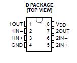
Pinout

  Connection Diagram


Specifications

Supply voltage range, VDD (see Note 1) . . . . . . . . . . . . . . . . . . . . . . . . . . . . . . . .  . . . . . . . . . 0.3 V to 18 V
Differential input voltage, VID (see Note 2) . . . . . . . . . . . . . . . . . . . . . . . . . . . . . . . . . . . . . . . . . . . . . . ±18 V
Input voltage range, VI . . . . . . . . . . . . . . . . . . . . . . . . . . . . . . . . . . . . . . . . . . . . . . . . . . . . . . . 0.3 V to VDD
Output voltage range, VO . . . . . . . . . . . . . . . . . . . . . . . . . . . . . . . . . . . . . . . . . . . . . . . . . . . . . 0.3 V to VDD
Input current, II . . . . . . . . . . . . . . . . . . . . . . . . . . . . . . . . . . . . . . . . . . . . . . . . . . . . . . . . . . . . . . . . . . . ±5 mA
Output current, IO (each output) . . . . . . . . . . . . . . . . . . . . . . . . . . . . . . . . . . . . . . . . . . . . . . . . . . . . . ±20 mA
Total supply current into VDD . . . . . . . . . . . . . . . . . . . . . . . . . . . . . . . . . . . . . .. . . . . . . . . . . . . . . . . . . . 40 mA
Total current out of GND . . . . . . . . . . . . . . . . . . . . . . . . . . . . . . . . . . . . . . . . . .. . . . . . . . . . . . . . . . . . . . 40 mA
Continuous total power dissipation . . . . . . . . . . . . . . . . . . . . . . . . . . . . . . . . . . . . See Dissipation Rating Table
Operating free-air temperature range, TA . . . . . . . . . . . . . . . . . . . . . . . . . . . . . . . . . . . . . . . 55°C to 125°C
Storage temperature range . . . . . . . . . . . . . . . . . . . . . . . . . . . . . . . . . . . . . . . . . . . . . . . . . . 65°C to 150°C
Lead temperature 1,6 mm (1/16 inch) from case for 10 seconds . . . . . . . . . . . . . . . . . . . . . . . . . . . . . . . 260°C
† Stresses beyond those listed under "absolute maximum ratings" may cause permanent damage to the device. These are stress ratings only, and functional operation of the device at these or any other conditions beyond those indicated under "recommended operating conditions" is not implied. Exposure to absolute-maximum-rated conditions for extended periods may affect device reliability.
NOTES: 1. All voltage values, except differential voltages, are with respect to network ground.
2. Differential voltages are at IN+ with respect to IN.


Description

The TLC3702 consists of two independent micropower voltage comparators designed to operate from a single supply and be compatible with modern HCMOS logic systems. They are functionally similar to the LM339 but use one-twentieth of the power for similar response times. The push-pull CMOS output stage of TLC3702-EP drives capacitive loads directly without a power-consuming pullup resistor to achieve the stated response time. Eliminating the pullup resistor not only reduces power dissipation, but also saves board space and component cost. The output stage of TLC3702-EP is also fully compatible with TTL requirements.

Texas Instruments LinCMOS process of TLC3702-EP offers superior analog performance to standard CMOS processes. Along with the standard CMOS advantages of low power without sacrificing speed, high input impedance, and low bias currents, the LinCMOS process offers extremely stable input offset voltages with large differential input voltages. This characteristic of TLC3702-EP makes it possible to build reliable CMOS comparators.


Customers Who Bought This Item Also Bought

Margin,quality,low-cost products with low minimum orders. Secure your online payments with SeekIC Buyer Protection.
Static Control, ESD, Clean Room Products
Test Equipment
Undefined Category
Tapes, Adhesives
803
Cable Assemblies
View more