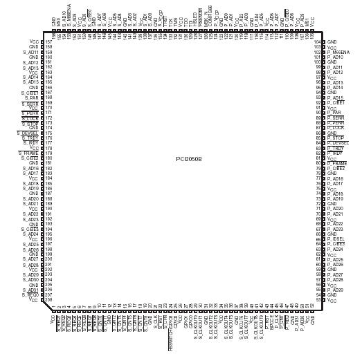
Features: • Two 32-bit, 66-MHz PCI buses
• 3.3-V core logic with universal PCI interfaces compatible with 3.3-V and 5-V PCI signaling environments
• Internal two-tier arbitration for up to nine secondary bus masters and supports an external secondary bus arbiter
• Ten secondary PCI clock outputs
• Independent read and write buffers for each direction
• Burst data transfers with pipeline architecture to maximize data throughput in both directions
• Supports write combing for enhanced data throughput
• Up to three delayed transactions in both directions
• Supports the frame-to-frame delay of only four PCI clocks from one bus to another
• Bus locking propagation
• Predictable latency per PCI Local Bus Specification
• Architecture configurable for PCI Bus Power Management Interface Specification
• CompactPCI hot-swap functionality
• Secondary bus is driven low during reset
• VGA/palette memory and I/O decoding options
• Advanced submicron, low-power CMOS technology
• 208-terminal PDV, 208-terminal PPM, or 257-terminal MicroStar BGA packagePinout SpecificationsSupply voltage range: VCC . . . . . . . . . . . . . . . . . . . . . . . . . . . . . . . . . . . . . . . . . . −0.5 V to 3.6 V
: P_VCCP . . . . . . . . . . . . . . . . . . . . . . . . . . . . . . . . . . . . . . . . .−0.5 V to 6 V
: S_VCCP. . . . . . . . . . . . . . . . . . . . . . . . . . . . . . . . . . . . . . . . . −0.5 V to 6 V
Input voltage range, VI: CMOS‡ . . . . . . . . . . . . . . . . . . . . . . . . . . . . . . . . . −0.5 V to VCC + 0.5 V
Input voltage range, VI: PCI§. . . . . . . . . . . . . . . . . . . . . . . . . . . . . . . . . . . . . . . . . −0.5 V to 6 V
Output voltage range, VO: CMOS‡ . . . . . . . . . . . . . . . . . . . . . . . . . . . . . . .. −0.5 V to VCC + 0.5 V
Output voltage range, VO: PCI§ . . . . . . . . . . . . . . . . . . . . . . . . . . . . . . . . .. . . . . . . .−0.5 V to 6 V
Input clamp current, IIK (VI < 0 or VI > VCC) (see Note 1). . . . . . . . . . . . . . . . . . . . . . . . . ±20 mA
Output clamp current, IOK (VO < 0 or VO > VCC) (see Note 2) . . . . . . . . . . . . . . . . . . . . . .±20 mA
Storage temperature range, Tstg . . . . . . . . . . . . . . . . . . . . . . . . . . . . . .. . . . . . . . .−65 to 150
Virtual junction temperature, TJ . . . . . . . . . . . . . . . . . . . . . . . . . . . . . . . . . . . . . . . . . . . . . . .150 DescriptionThe PCI2050B device is available in four packages, a 257-terminal GHK MicroStar BGA
TM package, a 257-terminal RoHS-compliant ZHK MicroStar BGA
TM package, a 208-terminal PDV package, or a 208-terminal PPM package. The GHK and ZHK PCI2050B packages are mechanically and electrically identical, but the ZHK is a RoHS-compliant design.
Throughout the remainder of PCI2050B, only the GHK package designator is used for either the GHK or the ZHK package. Figure 2−1 is the GHK-package terminal diagram. Figure 2−2 is the PDV-package terminal diagram.
Figure 2−3 is the PPM-package terminal diagram. Table 2−1 lists terminals on the PDV packaged PCI2050B in increasing numerical order with the signal name for each. Table 2−2 lists terminals on the PPM packaged device in increasing alphanumerical order with the signal name for each. Table 2−3 lists terminals on the GHK packaged device in increasing alphanumerical order with the signal name for each. Table 2−4, Table 2−5, and Table 2−6 list the signal names in alphabetical order, with corresponding terminal numbers for each package type.

 PCI2050B Data Sheet


