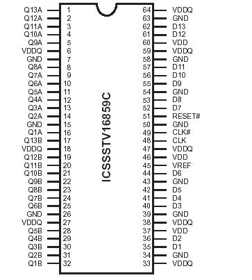
Features: • Differential clock signals• Meets SSTL_2 signal data• Supports SSTL_2 class II specifications on outputs• Low-voltage operation - VDD = 2.3V to 2.7V• Available in 64 pin TSSOP and 56 pin VFQFN (MLF2) packagesApplication• DDR Memory Modules• Pro...
ICSSSTV16859C: Features: • Differential clock signals• Meets SSTL_2 signal data• Supports SSTL_2 class II specifications on outputs• Low-voltage operation - VDD = 2.3V to 2.7V• Availa...
SeekIC Buyer Protection PLUS - newly updated for 2013!
268 Transactions
All payment methods are secure and covered by SeekIC Buyer Protection PLUS.
Features: • 25-bit 1:1 or 14-bit 1:2 configurable registered buffer• Supports SSTL_18 ...
Features: • 14-bit 1:2 registered buffer with parity check functionality• Supports SST...
Features: • 25-bit 1:1 or 14-bit 1:2 registered buffer with parity check functionality•...
The 13-bit-to-26-bit ICSSSTV16859C is a universal bus driver designed for 2.3V to 2.7V VDD operation and SSTL_2 I/O levels, except for the LVCMOS RESET# input.
Data flow from D to Q is controlled by the differential clock (CLK/CLK#) and a control signal (RESET#). The positive edge of CLK is used to trigger the data flow and CLK# is used to maintain sufficient noise margins where as RESET#,
an LVCMOS asynchronous signal, is intended for use at the time of power-up only. ICSSSTV16859C supports lowpower standby operation. A logic level "Low" at RESET# assures that all internal registers and outputs (Q) are reset to the logic "Low" state, and all input receivers, data (D) and clock (CLK/CLK#) are switched off. Please note that RESET# must always be supported with LVCMOS levels at a valid logic state because VREF may not be stable during power-up.
To ensure that outputs are at a defined logic state before a stable clock has been supplied, RESET# must be held at a logic "Low" level during power up.
In the DDR DIMM application of the ICSSSTV16859C, RESET# is specified to be completely asynchronous with respect to CLK and CLK#. Therefore, no timing relationship can be guaranteed between the two signals. When entering a low-power standby state, the register will be cleared and the outputs will be driven to a logic "Low" level quickly relative to the time to disable the differential input receivers. This ensures there are no glitches on the output. However, when coming out of low-power standby state, the register will become active quickly relative to the time to enable the differential input receivers. When the data inputs are at a logic level "Low" and the clock of the ICSSSTV16859C is stable during the "Low"-to-"High" transition of RESET# until the input receivers are fully enabled, the design ensures that the outputs will remain at a logic "Low" level.