Circuit Diagram
Index 2222
FeiDa PR-611C FM / AM radio schematic
Published:2011/3/23 3:43:00 Author:Joan | Keyword: FeiDa , FM / AM radio

Above is FeiDa PR-611C FM / AM radio schematic. (View)
View full Circuit Diagram | Comments | Reading(2794)
Heater circuit
Published:2011/3/23 3:44:00 Author:Joan | Keyword: Heater
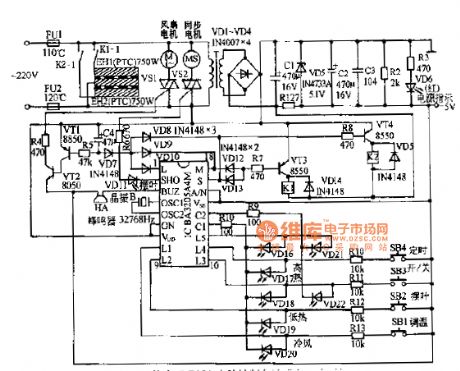
Above is Heater circuit. (View)
View full Circuit Diagram | Comments | Reading(504)
FuDian 710 UPS power driver board circuit
Published:2011/3/23 3:47:00 Author:Joan | Keyword: FuDian , UPS , power driver board
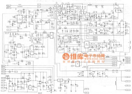
Above is FuDian 710 UPS power driver board circuit. (View)
View full Circuit Diagram | Comments | Reading(2057)
FuDian-Santak 710 UPS Power Driver Board Schematic
Published:2011/3/23 3:22:00 Author:Joan | Keyword: UPS Power Driver Board, FuDian-Santak

Above is FuDian-Santak 710 UPS Power Driver Board Schematic. (View)
View full Circuit Diagram | Comments | Reading(11641)
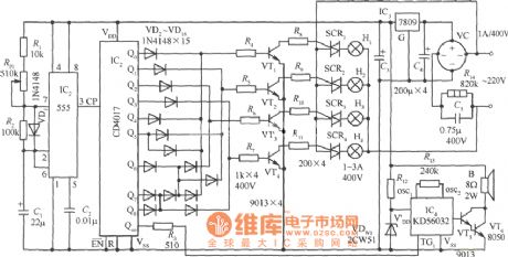
Four color lights power supply circuit with natural sound
Published:2011/3/21 1:31:00 Author:Joan | Keyword: Four color lights, power supply, natural sound
View full Circuit Diagram | Comments | Reading(502)
Common base amplifier dynamic analysis circuit
Published:2011/3/23 4:50:00 Author:Joan | Keyword: Common base , amplifier , dynamic analysis
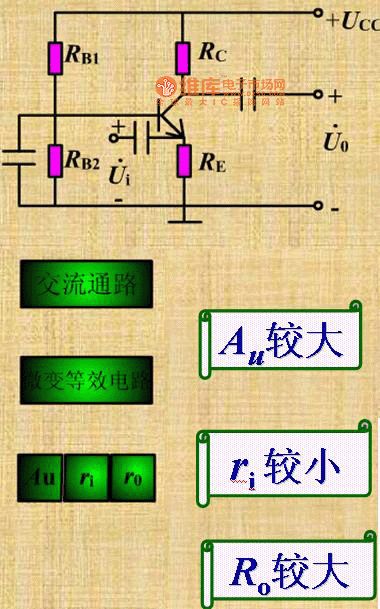
Below is Common base amplifier dynamic analysis circuit.
AC small signal equivalent circuit.
Au is comparatively large;ri is comparatively small;Ro is comparatively large. (View)
View full Circuit Diagram | Comments | Reading(622)
Common base amplifier static analysis circuit diagram
Published:2011/3/23 4:52:00 Author:Joan | Keyword: Common base , amplifier , static analysis
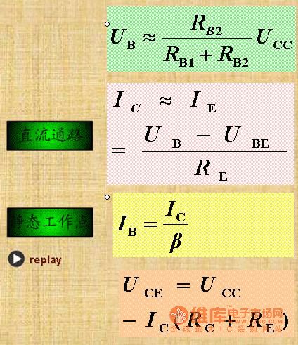
Below is Common base amplifier static analysis circuit diagram.
(View)
View full Circuit Diagram | Comments | Reading(634)
Common base amplifier circuit diagram
Published:2011/3/23 4:54:00 Author:Joan | Keyword: Common base , amplifier
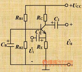
Below is Common base amplifier circuit diagram.
(View)
View full Circuit Diagram | Comments | Reading(1043)
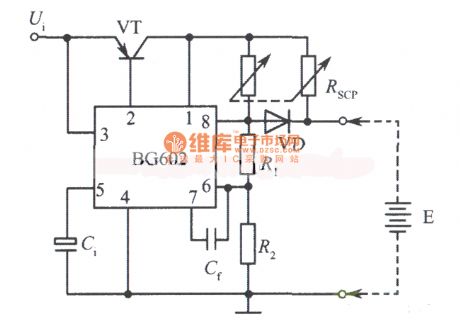
Charger circuit composed of BG602
Published:2011/3/21 1:52:00 Author:Joan | Keyword: Charger
View full Circuit Diagram | Comments | Reading(464)
Voice control switch circuit
Published:2011/3/23 2:52:00 Author:Joan | Keyword: Voice control , switch

Below is the Voice control switch circuit.
(View)
View full Circuit Diagram | Comments | Reading(1382)
RS232-TTL-RS485 interface converter circuit
Published:2011/3/21 1:27:00 Author:Joan | Keyword: RS232-TTL-RS485, interface converter

The above figure is RS232-TTL-RS485 interface converter circuit. (View)
View full Circuit Diagram | Comments | Reading(8101)
Jetta Air condition switch, blower, 2V motor circuit
Published:2011/3/23 1:18:00 Author:Joan | Keyword: Jetta , Air condition switch , blower , 2V motor
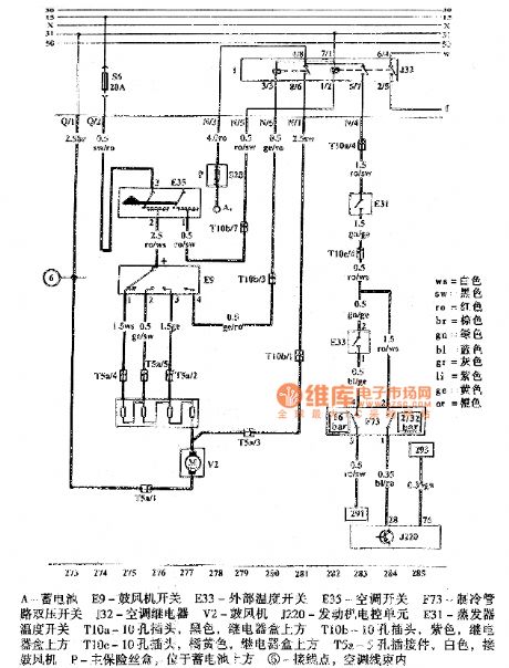
Above is Jetta Air condition switch, blower, 2V motor circuit.
A-BatteryE9-Blower switchE33-outside temperature switchE35-Air condition switchF73-Cooling pipe dual pressure switch J32-Air condition relayV2-BlowerJ220-Engine ECUE31-Evaporator temperature switchT10a-10-hole plug, black, in the top of the relay boxT10b-10-hole plug, purple, in the top of the relay boxT10c-10-hole plug, orange, in the top of the relay box T5a-5-hole connector, white, connect to blowerP-Main fuse box, located above the battery5-Connect point within the air condition wire harness (View)
View full Circuit Diagram | Comments | Reading(496)
Voice-activated circuit diagram
Published:2011/3/23 1:33:00 Author:Joan | Keyword: Voice-activated
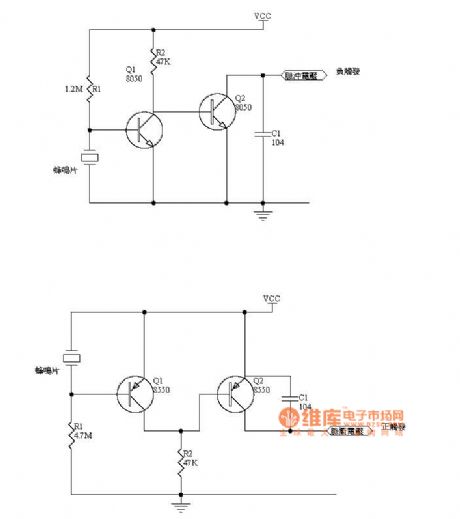
The figure is Voice-activated circuit diagram (View)
View full Circuit Diagram | Comments | Reading(971)
Self-made fast hand dryer circuit diagram 1
Published:2011/3/23 1:31:00 Author:Joan | Keyword: hand dryer

The figure is the self-made fast hand dryer circuit diagram 1.
(View)
View full Circuit Diagram | Comments | Reading(612)
LMl35 precision temperature measurement circuit
Published:2011/3/21 1:13:00 Author:Joan | Keyword: precision , temperature measurement

LMl35 series has equipped with outside correct terminal, which can easily correct measurement error and effectively eliminate the error caused by manufacturing process by simple correction method. As shown in Figure 4, when the temperature is 25 ℃, the adjustment potentiometer Rw changes the calibration terminal bias, until the sensor output voltage turns to 2.982V measured by a digital voltmeter in 20V output range. After calibration, the circuit's measurement error is less than 1 ℃ within the 0 to100C ℃ range. (View)
View full Circuit Diagram | Comments | Reading(593)
Jetta electromagnetic clutch pressure switch, radiator fan 5V motor circuit
Published:2011/3/21 1:14:00 Author:Joan | Keyword: Jetta , electromagnetic clutch , pressure switch, radiator fan , 5V motor

A-Battery F23-Refrigerant high orlow pressure switch E32-Cooling temperature switch E33-External temperature switch F18-Radiator fan thermal switch V7-Radiator fan J300-Motor ECU N25- Air condition electromagnetic clutch 7-Connecting point incar body wireharness (View)
View full Circuit Diagram | Comments | Reading(1396)
Jetta anti-theft system circuit
Published:2011/3/21 1:13:00 Author:Joan | Keyword: Jetta , anti-theft system
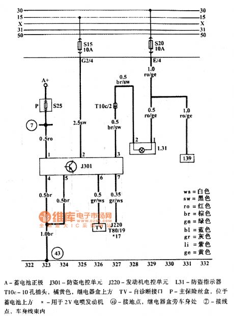
The figure is Jetta anti-theft systemcircuit.ws=whitesw=blackro=redbr=browngn=greenbl=bluegr=grayli=purplege=yellow
A-Battery J301-Anti-theft ECUJ220-Engine Electronic Control UnitL31-Anti-theft indicatorT10c-10-hole plug, orange, in the top of the relay boxTV-Self-diagnostic interfaceP-Main fuse box, located above the battery*-For 2V EFI engine43-Ground point, At the relay box next to the body7-Connection Point, Within the body harness (View)
View full Circuit Diagram | Comments | Reading(511)
Jetta central locking diagram
Published:2011/3/21 0:54:00 Author:Joan | Keyword: Jetta , central locking
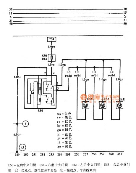
The figure is Jetta central locking diagram.
(View)
View full Circuit Diagram | Comments | Reading(891)
Jetta power and boot system schematic
Published:2011/3/21 0:54:00 Author:Joan | Keyword: power, boot system , Jetta
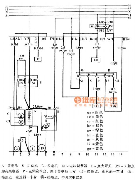
Above is Jetta power and boot system schematic. (View)
View full Circuit Diagram | Comments | Reading(401)
LM135 Ni-Cd battery fast charging circuit
Published:2011/3/21 0:52:00 Author:Joan | Keyword: Ni-Cd battery, fast charging

The figure is a safe and reliable Ni-Cd battery fast charging circuit. It detects the completion of battery chargeusing Ni-Cd battery case temperature change. In general, it has been already charge 80% of rated capacity when the rechargeable battery temperature rises to 5 ℃. ST1 is used to detect the ambient temperature, ST2 thermal coupled the rechargeable battery are used to detect the battery temperature. The offset terminal of the temperature sensor adjust ST1 output voltage 50mV higher than that of ST2. When the battery temperature exceeds 5 ℃ of the ambient temperature, the comparator LM308 output goes low, LM317change from constant current source state to the voltage source state, the output voltage is only about 2V, Power supply continues to charge the battery only through the R by 50mA small current. The method can save time and will not overcharge.
(View)
View full Circuit Diagram | Comments | Reading(1717)
| Pages:2222/2234 At 2022212222222322242225222622272228222922302231223222332234 |
Circuit Categories
power supply circuit
Amplifier Circuit
Basic Circuit
LED and Light Circuit
Sensor Circuit
Signal Processing
Electrical Equipment Circuit
Control Circuit
Remote Control Circuit
A/D-D/A Converter Circuit
Audio Circuit
Measuring and Test Circuit
Communication Circuit
Computer-Related Circuit
555 Circuit
Automotive Circuit
Repairing Circuit
