Circuit Diagram
Index 1979
Pressure measurement circuit diagram composed of OPO7
Published:2011/4/29 2:36:00 Author:Nicole | Keyword: Pressure measurement

The figure 1 is a pressure measurement circuit which is composed of OPO7. In the circuit, A2 uses Bi-FET input operational amplifier, when adjust potentiometer RP1, it can avoid the zero drift which is caused by bias current. A3 is initial balanced circuit and singal calibration circuit. The precision of amplifier is 0.5%, but the allowable bridge resistance precision is ±10%. In reality, it can be improved if take measures. The common-mode rejection ratio is about 90dB, 1kHz band noise is about 1~2μV(peak-peak value). It provides pressure sensor with constant current.
(View)
View full Circuit Diagram | Comments | Reading(1816)
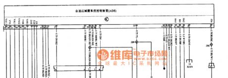
Benz W140 ADS system control computer circuit diagram
Published:2011/4/29 2:44:00 Author:Ecco | Keyword: Benz , ADS system , control, computer
View full Circuit Diagram | Comments | Reading(713)
Benz W140 (LH System Engine) ADS system circuit diagram
Published:2011/4/29 2:43:00 Author:Ecco | Keyword: Benz, LH System Engine, ADS system
View full Circuit Diagram | Comments | Reading(624)
DSM-872 Typical Application Circuit (b) circuit diagram
Published:2011/4/29 1:30:00 Author:Ecco | Keyword: Typical Application Circuit
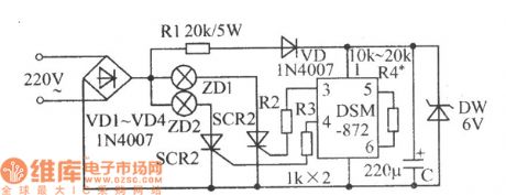
In the circuit shown as the chart, the high and low level of pin 3,pin 4 changes alternately, SCR1 and SCR2 will turn alternately, then the lamps will flash alternately.
(View)
View full Circuit Diagram | Comments | Reading(387)
DSM-872 Typical application circuit (1) circuit diagram
Published:2011/4/29 1:40:00 Author:Ecco | Keyword: Typical application circuit

In the circuit shown as the chart, the high and low level of pin 3,pin 4 changes alternately, the LED1 and LED2 will flash alternately.
(View)
View full Circuit Diagram | Comments | Reading(452)
TA7550S audio amplifier integrated circuit
Published:2011/4/29 1:30:00 Author:TaoXi | Keyword: audio amplifier

The TA75550S is designed as one kind of audio amplifier integrated circuit which is produced by the TOSHIBA company, and it can be used in large screen and rear projection TV such as the Konka BT5O01 rear projection TV.etc.
1.Features
The TA75550S has two-stage amplifier with the same functions. The two-stage op amp only supplies power to TA75550S, so the distortion is very small.
2.Pin functions and data
The TA75550S is in the 9-pin single in-line package, and the pin functions and data is as shown in table 1.
Table 1 The pin functions and data of TA75550S (View)
View full Circuit Diagram | Comments | Reading(576)
Low drift amplification circuit composed of TL592B
Published:2011/4/29 2:40:00 Author:TaoXi | Keyword: Low drift, amplification circuit

The Low drift amplification circuit composed of TL592B is as shown. (View)
View full Circuit Diagram | Comments | Reading(782)
TA8880CN light/color, line/field small signal processing integrated circuit
Published:2011/4/29 2:35:00 Author:TaoXi | Keyword: light/color, line/field, small signal processing
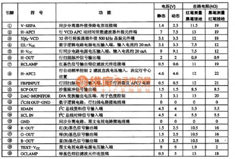

The TA8880CN is designed as one kind of light/color, line/field small signal processing integrated circuit which is produced by the TOSHIBA company, and it can be used in imported and domestic large screen color television sets.
1.Features
The TA8880CN has the brightness, chroma signal processing circuit, the line/field small signal processing integrated circuit, the I2C bus interface circuit, the color signal processing circuit, the graphic, screen display or picture in picture color signal processing circuit, the standard (PAL / NTSC / SECAM) identification and switching control circuit, and other circuit.
The TA8880 is in the 64-pin package, the pin functions and data is as shown in table 1.
Table 1 ThepinfunctionsanddataofTA8880CN (View)
View full Circuit Diagram | Comments | Reading(650)
TOYOTA COASTER coach seat belt alarm, rear window defrosting circuit wiring circuit diagram
Published:2011/4/29 1:50:00 Author:Nicole | Keyword: TOYOTA COASTER, coach, seat belt alarm, rear window defrosting
View full Circuit Diagram | Comments | Reading(1245)
Benz W129 (KE System Engine) ADS system circuit diagram
Published:2011/4/29 2:30:00 Author:Ecco | Keyword: Benz , KE System Engine, ADS system
View full Circuit Diagram | Comments | Reading(515)
Audio preamp circuit composed of DY336
Published:2011/4/29 2:22:00 Author:TaoXi | Keyword: Audio, preamp circuit

The audio preamp circuit supports the functions of signal switching, volume adjustment and buffer.etc, and you can add the 10 times voltage to amplify it to make the better sound quality.
One amplifier channel of the pre-amplifier is as shown. The circuit uses three DY336 low noise, high quality op amps. A1 is the input signal's buffer follower, it can reduces the burden of the signal source. The negative feedback volume controller is composed of the A2 and RPl, this kind of volume adjustment method can reduces the distortion and noise. Compare with the conventional volume control method, the transient distortion is smaller because of the no RC constant's integration effect. The output stage is composed of the A3, VTl and VT2, this stage works under the single-end A condition, the Single-end output contains even harmonics to make the sound quality better, and the current driving force of transistor is stronger, the low level control will be better.
(View)
View full Circuit Diagram | Comments | Reading(939)
Walkman bass upgrade circuit
Published:2011/4/29 1:22:00 Author:TaoXi | Keyword: Walkman, bass upgrade

The LAG665 and LAG668 are single cassette player IC, LAG668 is the improved mode of LAG665, their internal circuits are very similar. For the bass lovers, they can replace LAG665 with LAG668 and change the external circuits to upgrade the bass. Low frequency enhance measures is always to attenuate high or medium frequency. After the high or medium frequency has been attenuated, the signal falls off to influence audio sensitivity and dynamic effects, so the volume falls down and can not meet rated output power. The remedial measures are: 1.Improve the voltage gain of the front stage; 2. Increase the level of first voltage amplification; 3. Improve the rear level's input impedance to improve the input sensitivity by small stimulation; 4. Increase the gain of amplifier. The LAG668 uses the 3 and 4, the first: improve the rear stage's (attenuator) input impedance to 200kt2; the second: improve the power amplifier's voltage gain to 38dB. The Walkman bass upgrade circuit is as shown, channel 1's tone network is the same to channel's. (View)
View full Circuit Diagram | Comments | Reading(3436)
Packet Control Circuit of Chandelier
Published:2011/4/21 9:39:00 Author:Christina | Keyword: Packet Control

1.Operating Principle
The packet control circuit of chandelier is as Figure 1 shown, the function is as follows: when the power switch turned on, l1 group of lamp light; when the power switch turned on again, l1 and l2 group of lamp light; then the power switch still turned on, l1 and l3 group of lamp light; fourth operation, l1,l2 and l3 group of lamp light. If we continue to operate, the lanterns will be light over the order cycle again.
2.Installation
As the light control circuit is simple and has fewer components, we can make it into PCB before install it at the ceiling lamp's junction box. This circuit do not need to debug, just need to divide the chandelier lamps into three groups and connected correctly by this circuit. In the actual operation, you should avoid the voltage of c3 depleted.
(View)
View full Circuit Diagram | Comments | Reading(750)
Photo coupler data transmission circuit
Published:2011/4/24 8:49:00 Author:Nicole | Keyword: photo coupler, data transmission
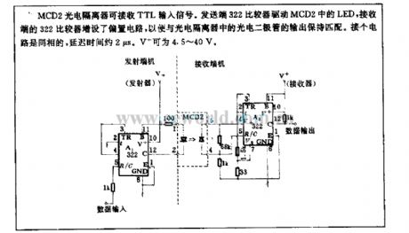
MCD2 photoelectric isolator can receive TTL input singal. Transmitter 322 comparator drives LED of MCD2, receiver 322 comparator is added bias circuit, then it can match with the photodiode output of photoelectric isolator. This circuit is inphase, the delay time is about 2μs. V+ can be 4.5~40V. (View)
View full Circuit Diagram | Comments | Reading(608)
1A transistor integrated circuit driven by photoisolator
Published:2011/4/27 9:42:00 Author:Nicole | Keyword: transistor, opto-electrical isolator drive

Any standard photoelectric isolator can produce enough output to meet the input current requirement of 1A power transistor. When it is without drive singal, R1 pulls in the Q1's base current, to keep it cut off. To add power supply to LED D1, then LM195 will be absolutely conducted by the insufficient 20μA current which is produced by photodiode D2. The power voltage can reach 42V. (View)
View full Circuit Diagram | Comments | Reading(506)
SE9518 multi-pattern program control color lamp control circuit
Published:2011/4/27 9:20:00 Author:Nicole | Keyword: program control, color lamp

SE9518 is CMOS multi-pattern program control decorative color lamp special integrated circuit, it has eight-way drive output and through the different level grouping of pattern choice terminal K0,K1,K2,K3 can achieve more than 20 kinds of color lamp flashing and jump patterns. The circuit is as shown, it consists of eight-way color lamp control circuit, firecrackers sound, power amplifier circuit, AC depressurization rectifier circuit and steady voltage circuit. (View)
View full Circuit Diagram | Comments | Reading(503)
74 series digital circuit 74155/156 and other 2 to 4 line decodes/demultiplexers
Published:2011/4/23 3:11:00 Author:May | Keyword: digital, 2 to 4 ine decodes, demultiplexers
View full Circuit Diagram | Comments | Reading(2495)
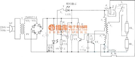
The power supply circuit of high efficient emergency light
Published:2011/4/23 3:14:00 Author:May | Keyword: power supply, high efficient, emergency light
View full Circuit Diagram | Comments | Reading(646)
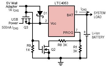
ltc4053 USB charger circuit diagram
Published:2011/4/23 3:13:00 Author:May | Keyword: USB charger
View full Circuit Diagram | Comments | Reading(748)
Self-adapting zero voltage switching electron ballast
Published:2011/4/23 3:37:00 Author:May | Keyword: self-adapting, zero voltage, switching, electron ballast

The principle diagram of self-adapting zero voltage switching electron ballast
IR2520 is mainly used for driving fluorescent lamp with power under 40W. The rated power of the lamp is different. The parameters of components such as Q1, Q2, L2, C7, etc have several differences. For example, when rated power of lighting tube is in the range of 16-28W, Q1 and Q2 should choose MOSFET which is 500V, 2A, such as (IRFC420, etc), the induction value of L2 is about 1.8mH and 3.5mH, the capacity of C7 is normally about 3.3nF-5.6nF. The power of lamp is larger, the induction of L2 is smaller, the real value is determined by debugging in order to close or meet the rated current of the lamp. (View)
View full Circuit Diagram | Comments | Reading(1591)
| Pages:1979/2234 At 2019611962196319641965196619671968196919701971197219731974197519761977197819791980Under 20 |
Circuit Categories
power supply circuit
Amplifier Circuit
Basic Circuit
LED and Light Circuit
Sensor Circuit
Signal Processing
Electrical Equipment Circuit
Control Circuit
Remote Control Circuit
A/D-D/A Converter Circuit
Audio Circuit
Measuring and Test Circuit
Communication Circuit
Computer-Related Circuit
555 Circuit
Automotive Circuit
Repairing Circuit
