
Circuit Diagram
Index 1963
telephone auto transponder circuit
Published:2011/5/3 19:25:00 Author:Christina | Keyword: telephone, auto transponder

The telephone auto transponder circuit is as shown in figure. IC2 is the 10 seconds voice recording circuit SR9G10A, if you press S2 to open the power, so you can entry the words which you want to tell your friends by the IC2's electret microphone. If you press Sl before go out for walk, the composite pipe's(is composed of the transistor VTl, VT2) electrode voltage VCE will be 0.65V, and the diode VD2 and transistor VT3 will not conduct.
When a call comes in, the phone ring's negative half cycle of ringing signal makes the ICl Optocoupler 4N35 conduction, IC2's PLAYE port is connected to ground to playback, one channel of the unilateral audio signal is amplified by the composite pipe to make transistor VT2's VCE increased, VD2, VT3 will conduct and relay JI will close to make the resistor Rl connects the external analog telephone (telephone's DC resistance is 300Ω); the other channel of unilateral audio signal adds to both ends of the telephone line, so your friends can hear your voice. After the sound finished, the circuit backs to the static state, relay J1 releases and the whole circuit is equivalent the hook.
(View)
View full Circuit Diagram | Comments | Reading(618)
Bridge Photo-detectors of photoresistance Circuit
Published:2011/5/3 23:51:00 Author:chopper | Keyword: photoresistance, Bridge, Photo-detectors

As shown in figure ,photoconductive resistance can form a bridge photo-detector in the industry photoelectric measuring device.Two of the same model (dark resistance equal) photoconductive resistanceact asbridge arms.One of them is used as photo-detectors;another sealed by black tape to avoid light as temperature compensation.This kind of Bridge Photo-detectors can use either dc or ac .When adopting ac modulation, it outputs for ac signal,which can reducenull shift of amplifier. (View)
View full Circuit Diagram | Comments | Reading(995)
The typical application circuit of LA4505 IC
Published:2011/5/3 22:44:00 Author:Ecco | Keyword: typical application , IC

The typical application circuit
The typical application circuit of LA4505 IC is shown as the chart, the left and right audio signals is input from the foot and pin ⑧ of LA4505 and it is amplified and output from ④ feet to drive the speaker power, and the power can reach ten 8W 8W (RL30).
(View)
View full Circuit Diagram | Comments | Reading(1120)
The brightness adjustment circuit diagram using coutesy switch
Published:2011/5/3 21:02:00 Author:Ecco | Keyword: brightness , coutesy switch

The brightness adjustment circuit diagram using coutesy switch(LX1970 visible light sensor) is shown as the chart. The circuit has the following characteristics: First, it uses a CMOS gate to control the LX1970 power, only when the gate outputs high level, LX1970 gets power, LX1970 is a micro-power device, so the power voltage can be provided by gate circuit; Second, the SRC end is connected a blocking diode in series (VD), when LX1970 power cuts off, VD stops, it can play a role of isolation, so that light signals can not be added to the LX1970, and it can play a protective role; Third, + 3.3V DC voltage signal and the PWM signal can be equivalent to the two logic or gate input signals, therefore, changing the DC voltage can also adjust the brightness. VD could choose 1N4148 high-speed switching silicon diode. (View)
View full Circuit Diagram | Comments | Reading(472)
The typical application circuit of LA76810 IC
Published:2011/5/3 20:28:00 Author:Ecco | Keyword: typical application circuit , IC

The typical application circuit
The typical application circuit of colorful TV composed of LA76810 IC is shown as the chart.
The typical application circuit of LA76810 IC is shown as the chart. (View)
View full Circuit Diagram | Comments | Reading(33650)
The internal block and typical application circuit diagram of LA7830 IC
Published:2011/5/3 20:34:00 Author:Ecco | Keyword: internal block , typical application circuit , IC

LA7830 IC includes field excitation, field output, field blanking circuit and overheat protection circuit and so on, the block diagram is shown as the chart.
The internal block and typical application circuit diagram of LA7830 IC is shown as the chart. (View)
View full Circuit Diagram | Comments | Reading(9248)
Motor steady speed typical application circuit diagram composed of LA5521 IC
Published:2011/5/3 20:51:00 Author:Ecco | Keyword: Motor, steady speed , typical application circuit, IC

The typical application circuit
Motor steady speed typical application circuit diagram composed of LA5521 IC is shown as the chart.
(View)
View full Circuit Diagram | Comments | Reading(698)
The typical application circuit diagram of LA5611 IC
Published:2011/5/3 20:48:00 Author:Ecco | Keyword: typical application circuit, IC

The typical application circuit
The power typical application circuit composed of LA5611 IC is shown as the chart.
The typical application circuit diagram of LA5611 IC is shown as the chart. (View)
View full Circuit Diagram | Comments | Reading(526)
Phone hang-up voice reminder circuit
Published:2011/5/3 9:36:00 Author:Christina | Keyword: Phone hang-up, voice reminder

With the increasing of living space, many families install some telephone extensions in different rooms, but the phone always can not be dialed in because one of the telephone extension does not hang. The phone hang-up voice reminder circuit is as shown, it can automatically issues the sound of call is not hung, please check the extensions to remind the user check the extensions.
(View)
View full Circuit Diagram | Comments | Reading(805)
TDAI512 End-Stage Amplifier Circuit
Published:2011/5/3 9:40:00 Author:Robert | Keyword: End-Stage Amplifier

TDAI512 End-Stage Amplifier Circuit is shown below. This circuits main technical data is listed here:
Output power, at RL=4ohms and
when Up=14.4V, k=0.5%, Po=18W;
when Up=14.4V, k=10%, Po=24W;
when Up=13.2V, k=0.5%, Po=15W;
when Up=13.2V, k=10%, Po=20W.
The amplification factor of voltage is Vu=100, which also means 40dB.
Bandwidth (3dB limit frequency): f=20Hz to 100KHz
Input voltage (Po=1W and RL=4ohms): Ui=20mV.
(View)
View full Circuit Diagram | Comments | Reading(482)
Beside-heating PTC water-cutoff component selection circuit
Published:2011/5/3 7:19:00 Author:Christina | Keyword: Beside-heating, PTC, water-cutoff, component selection

The relay's selection depends on the load power of the controlled equipment, this JQX-15F-B-type normally close contact-point relay is suitable for the mechanical & electrical equipments with the current lower than 12A. (View)
View full Circuit Diagram | Comments | Reading(804)
Gain Programmable Buffer Amplifier Used for Floating-point Change Circuit
Published:2011/5/3 8:52:00 Author:Joyce | Keyword: Gain, Programmable, Buffer Amplifier, Used for Floating-point Change, OPA676, ADC603
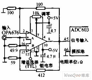
Gain programmable buffer amplifier used for floating-point change circuit is shown in the graph below.The strobe of channe A 、 B of OPA676 is controlled by 12-feet TTL logic level .The gain of channel A is 2,and that ofchannel B is 8. OPA676 uses ± 5 power supply, and is decoupled by two tantalum capacitance. It is set zero by a 10 KΩ potentiometer and compensated by a 39pF capacitance. This circuit can be connected with 12-bits 10MHz digital switching circuit ADC603.
(View)
View full Circuit Diagram | Comments | Reading(474)
Gain Controlled by Command Amplifier Circuit
Published:2011/5/3 9:03:00 Author:Joyce | Keyword: Gain, Controlled by Command, Amplifier
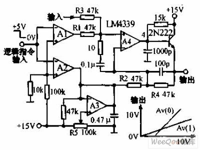
Gain controlled by command amplifier circuit is shown in the graph below.In phase lock return circuit,gain controlled by logic amplifier is needed . It consists of four comparators and a transistor . When the input instructions are high level, the gain Au is 1. When the input instructions is low level, the gain Au is 2. The bandwidth at full power which is 10Vp - p is 10KHz.
(View)
View full Circuit Diagram | Comments | Reading(503)
AC-DC automatic control and power distribution system using meter shape circuit diagram
Published:2011/5/3 4:33:00 Author:Ecco | Keyword: AC, DC , automatic control , power distribution system , meter , shape

AC-DC automatic control and power distribution system using meter shape circuit diagram is shown as the chart.
AC-DC automatic control and power distribution system using meter is suitable for installation in all kinds of the display panel and the board of automatic control systems and power distribution system to indicate electrical parameters such as AC and DC current, voltage, power factor, power, synchronization value, frequency, start voltage and overload current.
(View)
View full Circuit Diagram | Comments | Reading(884)
AC-DC automatic control and power distribution system using meter dimensions circuit diagram
Published:2011/5/3 4:30:00 Author:Ecco | Keyword: AC, DC , automatic control , power distribution system , meter , dimensions

AC-DC automatic control and power distribution system using meter dimensions circuit diagram is shown as the chart.
AC and DC power distribution system using meter is suitable for installation in all kinds of the display panel and the board of automatic control systems and power distribution system to indicate the related parameters. such as AC and DC current, voltage, power factor, power, synchronization value, frequency, start voltage and overload current.
(View)
View full Circuit Diagram | Comments | Reading(670)
uPC1241H Power Amplifier Ciecuit
Published:2011/5/3 9:30:00 Author:Felicity | Keyword: Power Amplifier Ciecuit

The picture above shows the uPC1241H Power Amplifier Circuit. (View)
View full Circuit Diagram | Comments | Reading(1053)
TDA8192 Power Amplifier Circuit
Published:2011/5/3 8:45:00 Author:Felicity | Keyword: Power Amplifier Circuit

The picture above shows the TDA8192 Power Amplifier Circuit. (View)
View full Circuit Diagram | Comments | Reading(747)
uPC1277H Power Amplifier Circuit
Published:2011/5/3 8:43:00 Author:Felicity | Keyword: Power Amplifier Circuit

The picture above shows the uPC1277H Power Amplifier Circuit. (View)
View full Circuit Diagram | Comments | Reading(1138)
Electronic Lark Song Circuit
Published:2011/5/3 19:30:00 Author:Sue | Keyword: Electronic, Lark Song

View full Circuit Diagram | Comments | Reading(728)
HAT1043M Internal Circuit
Published:2011/5/3 8:30:00 Author:Felicity | Keyword: Internal Circuit

The picture above shows the HAT1043M Internal Circuit. (View)
View full Circuit Diagram | Comments | Reading(388)
| Pages:1963/2234 At 2019611962196319641965196619671968196919701971197219731974197519761977197819791980Under 20 |
Circuit Categories
power supply circuit
Amplifier Circuit
Basic Circuit
LED and Light Circuit
Sensor Circuit
Signal Processing
Electrical Equipment Circuit
Control Circuit
Remote Control Circuit
A/D-D/A Converter Circuit
Audio Circuit
Measuring and Test Circuit
Communication Circuit
Computer-Related Circuit
555 Circuit
Automotive Circuit
Repairing Circuit