
Circuit Diagram
Index 193
Bidirectional I/O pin
Published:2013/1/25 1:16:00 Author:muriel | Keyword: Bidirectional I/O pin
View full Circuit Diagram | Comments | Reading(405)
Half-flying Capacitor Analog Multiplexer
Published:2013/1/25 1:16:00 Author:muriel | Keyword: Half-flying, Capacitor, Analog Multiplexer

View full Circuit Diagram | Comments | Reading(607)
Rapid heart rate meter (CD4518, CD4046, CD4511)
Published:2013/1/24 1:38:00 Author:Ecco | Keyword: Rapid , heart rate , meter
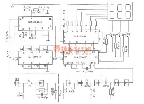
Heart rate meter and frequency meter are actually belong to the same class of measuring instruments, but heart rate meter's time the gate is just 1min rather than 1s. For A measuring instrument, 1 min measuring time is not only a long time, but it is difficult to ensure the accuracy of measurement. Therefore it must transform the measurement to match the rapid and accurate requirements. The figure shows a heart rate measuring instrument circuit, and it is consistent with the rapid and accurate requirements.
(View)
View full Circuit Diagram | Comments | Reading(3089)
The infrared pulse meter (NE555, CD4553, CD4543)
Published:2013/1/24 1:22:00 Author:Ecco | Keyword: infrared pulse meter

The so - called infrared pulse meter's sensor for picking up the signal uses infrared sensors. The circuit is shown as figure.
Figure (a) is the placement of the sensor and finger; (b) is schematic diagram; (c) is the Pin Function FIG of LM11, CD4049.
(View)
View full Circuit Diagram | Comments | Reading(2396)
The ceramic crystal Tester (CD4553, CD4040, CD4543)
Published:2013/1/24 1:18:00 Author:Ecco | Keyword: ceramic crystal Tester
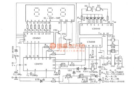
Ceramic crystal is the crystal oscillating element for infrared remote control transmitter, it has higher damage rate, and it is often difficult to determine whether it is good or bad in the overhaul. The detector shown in figure can quickly determine whether it is good or bad, so it provides a great convenience for overhaul. The instrument is actually a three-digit explicit frequency meter, and its reading unit is represented in kHz.
(View)
View full Circuit Diagram | Comments | Reading(5206)
Five-use tri-state audio logic pen ( CD4066 , 555 )
Published:2013/1/24 1:43:00 Author:Ecco | Keyword: Five-use, tri-state , audio logic pen , 555
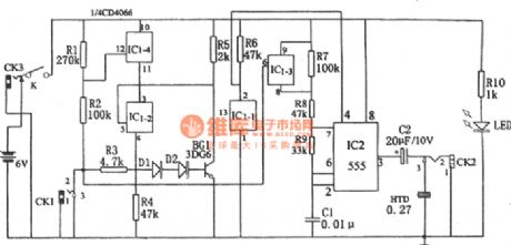
The circuit is mainly composed of multivibrator, four bidirectional switch CD4066 (IC1) and gate circuit with some resistive and capacitive components. The multivibrator 555 (IC2) consists of R7 , R8 , R9 and C1, and its oscillation frequency is affected by the off state of IC1-3.
(View)
View full Circuit Diagram | Comments | Reading(1306)
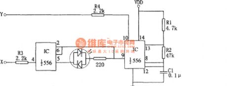
A simple second-tier logic state discriminator with 556
Published:2013/1/24 1:40:00 Author:Ecco | Keyword: simple, second-tier , logic state, discriminator , 556
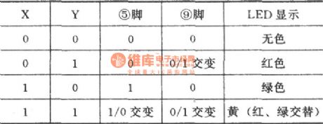
The relationship between light and logic state:
(View)
View full Circuit Diagram | Comments | Reading(579)
Transistors simple test circuit diagram
Published:2013/1/23 1:11:00 Author:Ecco | Keyword: Transistors, simple test
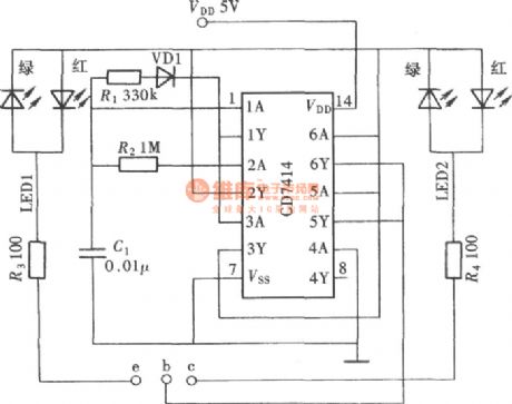
The transistor is one of the most commonly used devices in electronic circuits, and it is often to be tested, sometimes it is very troublesome to use a multimeter to test. The instrument is simple to manufacture, and the test results are very good, and it can fully meet the general requirements. The circuit schematic is shown as figure.
(View)
View full Circuit Diagram | Comments | Reading(1581)
Resistor quickly Estimating schematic with 555
Published:2013/1/23 2:17:00 Author:Ecco | Keyword: Resistor , quickly Estimating, 555
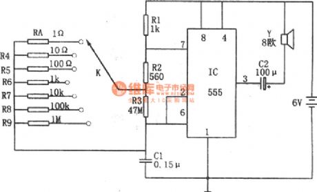
The core of circuit is a multivibrator composed of 555 and R1, R2, R3, Rx ( measured resistor ), C1, etc. The resistors R4 ~ R9 in circuit are the Estimating known resistors. The multivibrator output signals' period is T = 0.693 [ R1 +2 ( R2 + R3Rx / ( R3 + Rx ) ) ]. You can change the oscillation frequency by strobe switch K position, then the speaker issues different tone signals.
(View)
View full Circuit Diagram | Comments | Reading(1629)
The external output analog voltage conversion circuit of DAC0832
Published:2013/1/23 2:29:00 Author:Ecco | Keyword: external output, analog voltage conversion
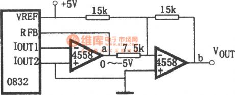
DAC0832 is a current output converter, if you need to get the analog voltage output, you must add an external converter circuit. The figure shows an analog voltage output circuit composed of two-stage operational amplifier. Unipolar analog voltage is output from the point a , and bipolar analog voltage is output from point b. If the reference voltage is +5 V, the point of a outputs 0 -5V voltage, and point b outputs ± 5V voltage.
(View)
View full Circuit Diagram | Comments | Reading(1287)
The connection method of AD7520 basic circuit
Published:2013/1/23 2:33:00 Author:Ecco | Keyword: connection method , basic circuit
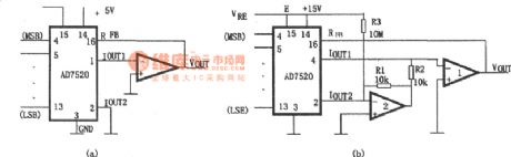
The AD7520 is an inexpensive, medium - resolution D / A converter chip, and it is composed of CMOS current switch and T resistor network, it has a simple structure, flexible configuration and good versatility. The connection method of the AD7520 basic circuit is shown as figure, wherein the figure (a) is a unipolar output basic conversion circuit; Figure (b) is the basic conversion circuit of the bipolar output.
(View)
View full Circuit Diagram | Comments | Reading(763)
DC capacitor tester with 555
Published:2013/1/23 2:36:00 Author:Ecco | Keyword: DC capacitor tester, 555
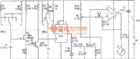
The tester is composed of the pulse generator, monostable trigger, DC amplifier and header indicating circuit. It can measure npF to 10μF capacitance. The range is divided into 0 ~ 100PF, 0 ~ 1nF, 0 ~ 10nF, 0 ~ 100nF, 0 ~ 1μF, 0 ~ 10μF.
(View)
View full Circuit Diagram | Comments | Reading(1660)
Analog regulator
Published:2013/1/22 21:22:00 Author:muriel | Keyword: Analog regulator

View full Circuit Diagram | Comments | Reading(663)
basic converter
Published:2013/1/22 21:21:00 Author:muriel | Keyword: basic converter

View full Circuit Diagram | Comments | Reading(1286)
5 volt to +24V flyback output DC to DC Converter
Published:2013/1/22 21:21:00 Author:muriel | Keyword: 5 volt to +24V , flyback output, DC to DC Converter

View full Circuit Diagram | Comments | Reading(1199)
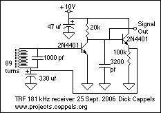
simple TRF receiver
Published:2013/1/22 21:21:00 Author:muriel | Keyword: simple, TRF receiver
View full Circuit Diagram | Comments | Reading(0)
RF Transmission and detection/measurement example
Published:2013/1/22 21:20:00 Author:muriel | Keyword: RF Transmission , detection, measurement
View full Circuit Diagram | Comments | Reading(811)
Switched resistor modulator 2
Published:2013/1/22 21:19:00 Author:muriel | Keyword: Switched, resistor modulator

View full Circuit Diagram | Comments | Reading(710)
Switched resistor modulator
Published:2013/1/22 21:18:00 Author:muriel | Keyword: Switched , resistor modulator

View full Circuit Diagram | Comments | Reading(736)
infrared beacon
Published:2013/1/22 21:17:00 Author:muriel | Keyword: infrared beacon

View full Circuit Diagram | Comments | Reading(741)
| Pages:193/2234 At 20181182183184185186187188189190191192193194195196197198199200Under 20 |
Circuit Categories
power supply circuit
Amplifier Circuit
Basic Circuit
LED and Light Circuit
Sensor Circuit
Signal Processing
Electrical Equipment Circuit
Control Circuit
Remote Control Circuit
A/D-D/A Converter Circuit
Audio Circuit
Measuring and Test Circuit
Communication Circuit
Computer-Related Circuit
555 Circuit
Automotive Circuit
Repairing Circuit