
Circuit Diagram
Index 1583
BMW anti-lock braking system circuit
Published:2011/7/8 5:28:00 Author:Christina | Keyword: BMW, anti-lock braking system

View full Circuit Diagram | Comments | Reading(569)
BMW gear box circuit
Published:2011/7/8 5:27:00 Author:Christina | Keyword: BMW, gear box

View full Circuit Diagram | Comments | Reading(480)
The High input-high output integrated voltage stabilization power supply circuit (4)
Published:2011/7/8 5:26:00 Author:Christina | Keyword: High input, high output, integrated, voltage stabilization, power supply

View full Circuit Diagram | Comments | Reading(455)
BMW charging circuit
Published:2011/7/8 5:29:00 Author:Christina | Keyword: BMW, charging circuit

View full Circuit Diagram | Comments | Reading(545)
Starting insurance for starting injection and running out circuit
Published:2011/7/5 10:32:00 Author:John
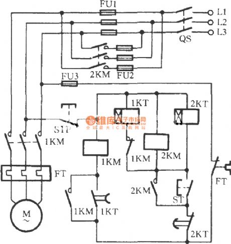
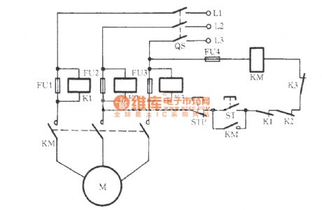
Three-phase motor’s starting current is large, which is generally three times more of the motor’s rated current. If the chosen fuse (also known as fuse) is with a larger rated current, it is rater detrimental to the protection for the motor. The phenomenon of frequent burning of insurance frequently occurs even if it is in the right size. The circuit as shown can be used to resolve this contradiction. As for the figure, FU1 is the motor main fuse with the right size and FU2 is a launching insurance. Rated current of FU1 should be equal to the motor’s rated current. And rated current of FU2 is generally equals to that of the FU1.
(View)
View full Circuit Diagram | Comments | Reading(746)
Exhaust fan automatically starting circuit
Published:2011/7/5 8:56:00 Author:John | Keyword: Exhaust fan
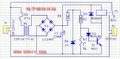
The circuit is as shown. 220-volt power supply is divided into two routes. One route is transferred into a 5V power supply through the transformer, aiming to supply the control circuit. The other route is connected to the exhaust fan through the relay in series. As for control circuit, the 5-volt power supply gets DC power supply through the rectifier. Commonly, R3, the partial pressure of R3 can not be the transistor due to a smaller resistance. So the relay is not energized and the exhaust fan does not work. When the heater is heated, heat resistance of R3 becomes larger. And the partial pressure on the R3 would induct the transistor. Then the relay pulls and exhaust fan works. (View)
View full Circuit Diagram | Comments | Reading(1482)
Three non-steady-state circuit 1
Published:2011/7/8 9:37:00 Author:Lucas | Keyword: Three non-steady-state

View full Circuit Diagram | Comments | Reading(477)
three contactors for consisting Y-△ buck starting circuit
Published:2011/7/10 3:09:00 Author:Lucas | Keyword: contactor
View full Circuit Diagram | Comments | Reading(662)
Three-phase motor dual-speed 2Y / △ connection with indicator regulator circuit
Published:2011/7/10 2:46:00 Author:Lucas | Keyword: Three-phase motor, indicator
The circuit increases the low speed indicator H △ and high-speed indicator H2Y. When the motor stops, the two lights are not lighted.
(View)
View full Circuit Diagram | Comments | Reading(8032)
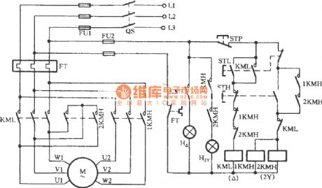
Three-phase motor dual-speed 2Y / △ connection speed control circuit (a)
Published:2011/7/10 2:54:00 Author:Lucas | Keyword: 2KMH, Three-phase motor, 2Y / △ connection
There are three AC contactors used in the circuit. The button STH is the high-speed control button. When it is pressed, AC contactor 1KMH and 2KMH suctions at the same time, thus driving the motor M for high-speed (2Y) operation. The button STL is the low-speed control button. When it is pressed, AC contactor KML suctions to drive the motor M for low-speed (△) operation. When the button STP is pressed, the motor stops running. FT is a thermal relay for overload protection.
(View)
View full Circuit Diagram | Comments | Reading(11497)
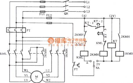
Three-phase motor dual-speed 2Y / △ connection automatic speed control circuit
Published:2011/7/10 2:56:00 Author:Lucas | Keyword: Three-phase motor, 2Y / △ connection
View full Circuit Diagram | Comments | Reading(4333)
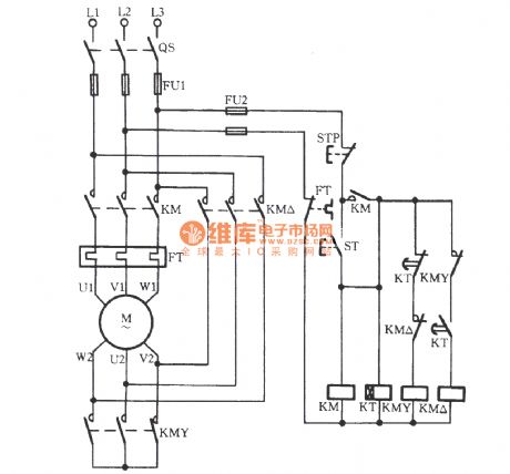
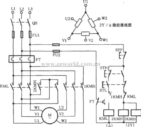
Three-phase motor double speed 2Y / Y connection speed regulation circuit
Published:2011/7/10 1:17:00 Author:Lucas | Keyword: Three-phase motor , double speed , 2Y / Y connection , speed regulation

When you press the start button STL, the AC contactor KML gets electric, then the motor M is connected as Y; when you press STH, the AC contactors 1KMH and 2KMH get power to pull in, then the motor M is connected as 2Y to operate in high speed. STP is stop button for the machine.
(View)
View full Circuit Diagram | Comments | Reading(8017)
△-shaped three-phase motor buck starting circuit
Published:2011/7/10 3:07:00 Author:Lucas | Keyword: three-phase motor
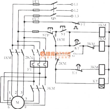
The start button ST is pressed to drive the 1KM coil to gain electricity and to be self-protected. At the same time, 3KM relay coil KT gains electricity and motor’s windings are connected to form a extending triangle for buck starting. When the Kt's tuning time reaches, the delaying normally closed contacts disconnect. Then the 3KM coil releases with the loss of power and its normally closed auxiliary contact is closed. Meanwhile, KT’s delaying closing normally opened contacts are closed. The 2KM coil gains electricity to suction and to be self-locked. 3KM’s main contact releases while 2KM’s main contact closes. Then the motor windings are transferred from extending triangle shape into a triangle connection. The starting process is over and the operation is on.
(View)
View full Circuit Diagram | Comments | Reading(1958)
Rongshida XPB50-l88S tube washing machine circuit
Published:2011/7/8 9:41:00 Author:Lucas | Keyword: Rongshida , tube washing machine

View full Circuit Diagram | Comments | Reading(1997)
Fuse voltage control signal relay open-phase protection circuit
Published:2011/7/10 Author:Lucas | Keyword: Fuse voltage , control signal, relay , open-phase protection
View full Circuit Diagram | Comments | Reading(1017)
Three non-steady-state circuit 2
Published:2011/7/8 9:37:00 Author:Lucas | Keyword: Three non-steady-state

View full Circuit Diagram | Comments | Reading(418)
Three-phase motor for extend the △ access to single-phase operation circuit
Published:2011/7/9 9:34:00 Author:Lucas | Keyword: Three-phase motor
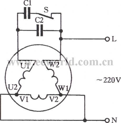
Extension three-phase motor with △-connection is suitable for 220V or 380V single-phase power operation. The circuit is shown below. The principle of this connection is the same to that of Y-connection, but there are some differences either. (1) It can be seen from the figure that only one U phase-phase winding is the main winding among the motor windings. And the V phase and W phase are connected in series as auxiliary windings. (2) Winding U and winding V, W form an autotransformer. Due to the boosting function of the autotransformer, capacitors C1 and C2 are exposed to bear voltage which is three times of that of the single-phase power supply. As a result, a capacitor with a high working voltage is needed to be used, such as a capacitor of 1000V.
(View)
View full Circuit Diagram | Comments | Reading(2093)
Three-phase motor braking circuit 2
Published:2011/7/8 22:48:00 Author:Lucas | Keyword: Three-phase , motor braking

When braking, you should press the stop button STP, then AC contactor KMF (or KMR, KMF is forward contactor, KMR is the reverse contactor, 1SA, 2SA are the trip switches) loses power and releases, the motor M leaves from the AC power supply, and the normally closed contact KMF or KMR restores closed state, and KM coil gets electric and pulls in, and the main contacts close, then AC is added to the M stator windings by the main contact of KM and rectified into DC by the rectifier diodes VD1, VD2 to make motor brake quickly. At this time, due to KMF's (or KMR) normally open auxiliary contact is disconnected, the time relay KT coil is energized.
(View)
View full Circuit Diagram | Comments | Reading(3516)
three-phase motor with 36V low-voltage control circuit
Published:2011/7/10 2:36:00 Author:Lucas | Keyword: three-phase motor
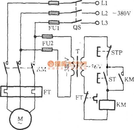
Just as shown in the circuit, the motor is a full-voltage direct starting circuit. And its control circuit’s power supply is the AC voltage reduced by the transformer T from 380V to 36V. Therefore, the AC contactor’s coil voltage must be 36V. In wet or such situations, the security has been ensured.
(View)
View full Circuit Diagram | Comments | Reading(3118)
reversible controlling point of the three-phase motor short brake circuit
Published:2011/7/9 9:47:00 Author:Lucas | Keyword: three-phase motor
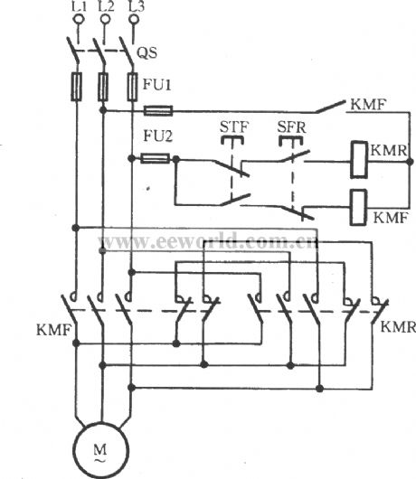
The circuit is shown. When STR is pressed, the reverse contactor KMR pulls to disconnect the braking short contacts (KMR’s normally closed contacts), thus driving the motor to run reversely. When STR is released, the contactor releases with the loss of power. And the main contact KMR is off. At this time, braking short contacts restore the closed state to drive the stator coil to produces the M braking torque for braking. Similarly, forward braking operation is done with the same methods and principles as described above. This brake circuit is only applies for small motors below 3kW.
(View)
View full Circuit Diagram | Comments | Reading(2012)
| Pages:1583/2234 At 2015811582158315841585158615871588158915901591159215931594159515961597159815991600Under 20 |
Circuit Categories
power supply circuit
Amplifier Circuit
Basic Circuit
LED and Light Circuit
Sensor Circuit
Signal Processing
Electrical Equipment Circuit
Control Circuit
Remote Control Circuit
A/D-D/A Converter Circuit
Audio Circuit
Measuring and Test Circuit
Communication Circuit
Computer-Related Circuit
555 Circuit
Automotive Circuit
Repairing Circuit