Relay Control
Exhaust fan automatically starting circuit
Published:2011/7/5 8:56:00 Author:John | Keyword: Exhaust fan | From:SeekIC


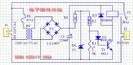
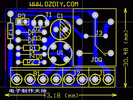
The circuit is as shown. 220-volt power supply is divided into two routes. One route is transferred into a 5V power supply through the transformer, aiming to supply the control circuit. The other route is connected to the exhaust fan through the relay in series. As for control circuit, the 5-volt power supply gets DC power supply through the rectifier. Commonly, R3, the partial pressure of R3 can not be the transistor due to a smaller resistance. So the relay is not energized and the exhaust fan does not work. When the heater is heated, heat resistance of R3 becomes larger. And the partial pressure on the R3 would induct the transistor. Then the relay pulls and exhaust fan works.
Reprinted Url Of This Article:
http://www.seekic.com/circuit_diagram/Control_Circuit/Relay_Control/Exhaust_fan_automatically_starting_circuit.html
Print this Page | Comments | Reading(3)

Article Categories
power supply circuit
Amplifier Circuit
Basic Circuit
LED and Light Circuit
Sensor Circuit
Signal Processing
Electrical Equipment Circuit
Control Circuit
Remote Control Circuit
A/D-D/A Converter Circuit
Audio Circuit
Measuring and Test Circuit
Communication Circuit
Computer-Related Circuit
555 Circuit
Automotive Circuit
Repairing Circuit
Code: