
Circuit Diagram
Index 119
piezo speaker
Published:2013/5/9 21:40:00 Author:muriel | Keyword: piezo speaker

View full Circuit Diagram | Comments | Reading(711)
3 Volt Geiger Counter Power Supply
Published:2013/5/9 21:40:00 Author:muriel | Keyword: 3 Volt , Geiger Counter , Power Supply
View full Circuit Diagram | Comments | Reading(1545)
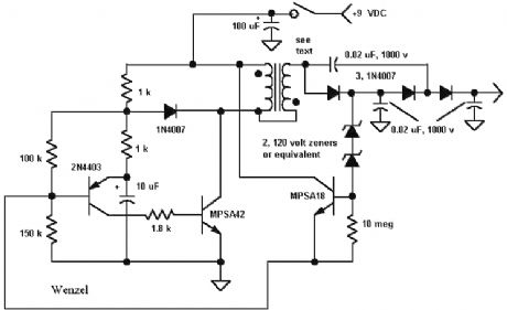
9 Volt Geiger Counter Power Supply
Published:2013/5/9 21:39:00 Author:muriel | Keyword: 9 Volt , Geiger Counter, Power Supply
View full Circuit Diagram | Comments | Reading(1887)
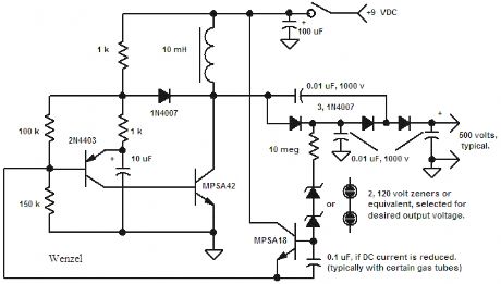
500 Volt Geiger Counter Power Supply
Published:2013/5/9 21:39:00 Author:muriel | Keyword: 500 Volt, Geiger Counter , Power Supply
View full Circuit Diagram | Comments | Reading(1113)
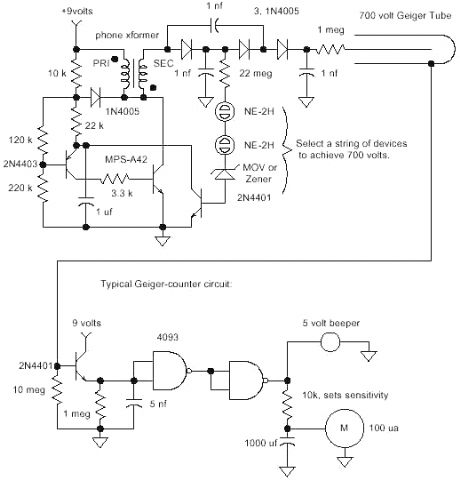
basic Geiger counter circuit
Published:2013/5/9 21:38:00 Author:muriel | Keyword: basic Geiger counter circuit
View full Circuit Diagram | Comments | Reading(690)
A basic Geiger counter circuit
Published:2013/5/9 21:36:00 Author:muriel | Keyword: basic Geiger counter circuit

The circuit below is designed to achieve low power consumption - less than 1mA - for extended battery operation, while being relatively stable and easy to build. None of the component values are especially critical, and it is possible to use other transformer designs. For best efficiency, the value of oscillator capacitor C3 should be adjusted to resonate the transformer. If you don't have an oscilloscope available to help you with this, you can get a fairly good result by scaling up C3 roughly in proportion with the primary inductance. You can estimate this from the quoted specific inductance of the core, multiplied by the number of primary turns squared. The transformer is probably the trickiest bit to make, but it's worth doing well. You may struggle to find suitable commercial parts with this turns ratio, although it is just about possible to press a small mains transformer into service by using it in reverse. The efficiency will be fairly low, though.
(View)
View full Circuit Diagram | Comments | Reading(927)
Geiger counter
Published:2013/5/9 21:35:00 Author:muriel | Keyword: Geiger counter

View full Circuit Diagram | Comments | Reading(4893)
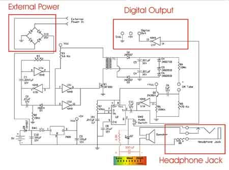
4049 Hex Inverting Buffer
Published:2013/5/9 21:34:00 Author:muriel | Keyword: 4049 Hex Inverting Buffer

The circuit is shown in Figure 4. The 4049 Hex Inverting Buffer is set up as a square wave generator. The power MOSFET IRF830 switches the current on and off to the primary windings of the mini step-up transformer. The output of the mini step-up transformer is fed to a voltage doubler consisting of two high voltage diodes D2 and D3 and two high voltage capacitors C4 and C5.
The high voltage output from this stage is regulated to 500 volts needed for our GM tube by three zener diodes stacked one on top of the other (D4, D5 and D6). Diodes D5 and D6 are 200V zener diodes and diode D4 is a 100-Volt zener. Together (200 + 200 + 100 = 500), they equal 500 volts. Five hundred volts is the optimum operating voltage for our GM Tube.
The 500-volt regulated output is fed to the anode of the GM tube through a current limiting 10 mega-ohm resistor R4. The 10 mega-ohm resistor limits the current through the GM tube and helps quench the avalanched ionization when a radioactive particle is detected.
The cathode of the tube is connected to a 470K (R5) resistor. The voltage pulse across R5 generated by the detection of radiation, feeds to the base of a 2N3904 NPN transistor, through a 1-uF capacitor (C6).
The NPN transistor clamps the output pulse from the GM tube to Vcc and feeds it to an inverting gate on the 4049. The inverted pulse signal from the gate is a trigger to the 555 Timer. The timer is set up in monostable mode that stretches out the pulse received on its trigger. The output pulse from the timer flashes the LED and outputs an audible click to the speaker via pin 3. (View)
View full Circuit Diagram | Comments | Reading(1565)
Thermostat for room heater 2
Published:2013/5/9 21:30:00 Author:muriel | Keyword: Thermostat, room heater

View full Circuit Diagram | Comments | Reading(1173)
Plant watering timer 2
Published:2013/5/9 21:30:00 Author:muriel | Keyword: Plant watering timer

View full Circuit Diagram | Comments | Reading(921)
Mercury battery replacement
Published:2013/5/9 21:29:00 Author:muriel | Keyword: Mercury battery replacement

View full Circuit Diagram | Comments | Reading(649)
Photo film processor
Published:2013/5/9 21:28:00 Author:muriel | Keyword: Photo film processor

View full Circuit Diagram | Comments | Reading(854)
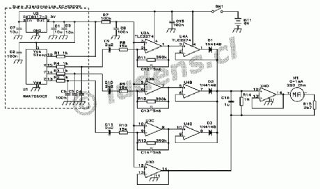
Accelerometer
Published:2013/5/9 21:27:00 Author:muriel | Keyword: Accelerometer
View full Circuit Diagram | Comments | Reading(1312)
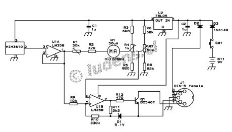
A simple handheld hygrometer
Published:2013/5/9 21:27:00 Author:muriel | Keyword: A simple handheld hygrometer
View full Circuit Diagram | Comments | Reading(1149)
An Equivalent Series Resistance Meter
Published:2013/5/9 21:26:00 Author:muriel | Keyword: Equivalent Series , Resistance Meter

View full Circuit Diagram | Comments | Reading(1413)
The 80 Watt power amplifier
Published:2013/5/9 21:25:00 Author:muriel | Keyword: The 80 Watt power, amplifier

View full Circuit Diagram | Comments | Reading(1909)
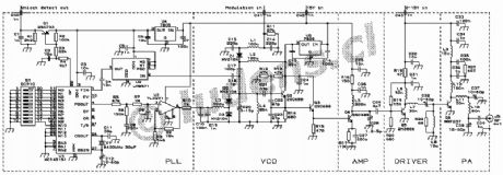
The synthesized exciter
Published:2013/5/9 21:25:00 Author:muriel | Keyword: The synthesized exciter
View full Circuit Diagram | Comments | Reading(886)
80 Watt FM stereo broadcast transmitter
Published:2013/5/9 21:25:00 Author:muriel | Keyword: 80 Watt, FM , stereo broadcast transmitter

View full Circuit Diagram | Comments | Reading(929)
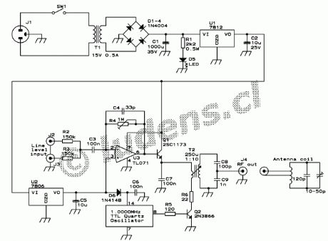
Small AM transmitter
Published:2013/5/9 21:24:00 Author:muriel | Keyword: Small AM transmitter
View full Circuit Diagram | Comments | Reading(815)
Voice identifier for a repeater station
Published:2013/5/9 21:24:00 Author:muriel | Keyword: Voice identifier, repeater station

View full Circuit Diagram | Comments | Reading(1073)
| Pages:119/2234 At 20101102103104105106107108109110111112113114115116117118119120Under 20 |
Circuit Categories
power supply circuit
Amplifier Circuit
Basic Circuit
LED and Light Circuit
Sensor Circuit
Signal Processing
Electrical Equipment Circuit
Control Circuit
Remote Control Circuit
A/D-D/A Converter Circuit
Audio Circuit
Measuring and Test Circuit
Communication Circuit
Computer-Related Circuit
555 Circuit
Automotive Circuit
Repairing Circuit