


About SeekIC | Services | Payment | Advertisements service | Contact Us | Links
© 2008-2012 SeekIC.com Corp.All Rights Reserved.

Published:2013/5/16 2:03:00 Author:muriel | Keyword: LM555 Timer
View full Circuit Diagram | Comments | Reading(1138)
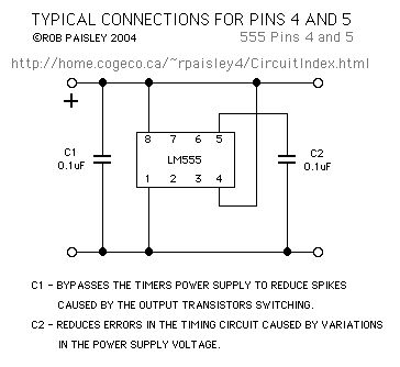
Published:2013/5/16 2:03:00 Author:muriel | Keyword: LM555 Timer
View full Circuit Diagram | Comments | Reading(858)
Published:2013/5/16 2:03:00 Author:muriel | Keyword: LM555 , Astable Oscillator
View full Circuit Diagram | Comments | Reading(720)
Published:2013/5/16 2:02:00 Author:muriel | Keyword: LM555, Monostable Oscillator
View full Circuit Diagram | Comments | Reading(1042)
Published:2013/5/16 2:02:00 Author:muriel | Keyword: RESET And CONTROL Terminal Notes
View full Circuit Diagram | Comments | Reading(749)
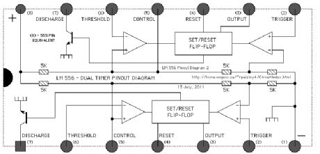
Published:2013/5/16 2:01:00 Author:muriel | Keyword: LM556 , Timer Internal Circuit
View full Circuit Diagram | Comments | Reading(1204)
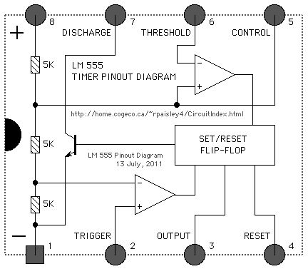
Published:2013/5/16 2:01:00 Author:muriel | Keyword: LM555 , Timer Internal Circuit
View full Circuit Diagram | Comments | Reading(838)
Published:2013/5/16 2:00:00 Author:muriel | Keyword: LM555 Timer Internal Circuit
View full Circuit Diagram | Comments | Reading(2205)
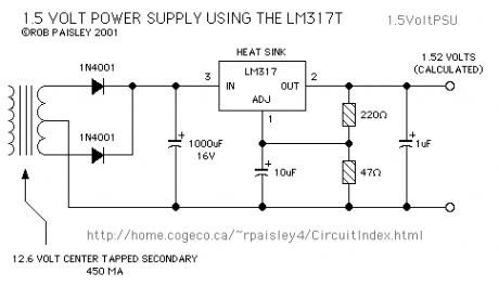
Published:2013/5/16 1:59:00 Author:muriel | Keyword: 1.5 Volt, Power Supply , LM317
View full Circuit Diagram | Comments | Reading(2640)
Published:2013/5/16 1:59:00 Author:muriel | Keyword: Test Bench Power Supply
View full Circuit Diagram | Comments | Reading(1169)
Published:2013/5/16 1:58:00 Author:muriel | Keyword: Fixed Voltage Regulators
View full Circuit Diagram | Comments | Reading(621)
Published:2013/5/16 1:58:00 Author:muriel | Keyword: Generally, plug-in transformers
View full Circuit Diagram | Comments | Reading(526)
Published:2013/5/16 1:56:00 Author:muriel | Keyword: LM311 Comparator , Controlled H-Bridge schematic
View full Circuit Diagram | Comments | Reading(1609)
Published:2013/5/16 1:56:00 Author:muriel | Keyword: 3Amp, DCC Booster Circuit
View full Circuit Diagram | Comments | Reading(803)
Published:2013/5/16 1:55:00 Author:muriel | Keyword: Low Voltage H-bridge
View full Circuit Diagram | Comments | Reading(796)
Published:2013/5/16 1:52:00 Author:muriel | Keyword: -5VDC from +5VDC

If you happen to have the March 1984 issue of Radio-Electronics, turn to page 78. This issue has the very first instalment of Robert Grossblatt's Designer's Notebook column. In it, he shows a simple circuit which will supply a negative voltage, given a positive voltage. It's basically a 555-based oscillator, and a voltage-doubling rectifier. He claims the negative-voltage output should be good for about 60ma. No-load voltage should be pretty close to the input voltage (but negative), although the voltage will drop a bit, depending on the load. If you put +5V into the circuit, it'll give you around -5V out. load. If you put +5V into the circuit, it'll give you around -5V out. If the load makes the voltage drop too low (-3V or -4V), you could always just feed the circuit with a higher voltage (like maybe 9V or 12V) and then just regulate the output down to -5V using a 7905 regulator. I've used this circuit a couple of times for powering op-amp's, and it works great!
I'm not that great at ASCII-art, but I'll give it a shot. If the following schematic doesn't make sense, let me know, and I'll try it again...Note: In the above diagram , both diodes point down (the anodes are at the top). Also, watch the polarity of C1 & C3.
The circuit is set up to oscillate at about 45kHz, with a duty cycle pretty close to 50%. None of the values of any of the parts are terribly critical, so if the capacitors or resistors are in the ballpark , it should still work okay. (View)
View full Circuit Diagram | Comments | Reading(671)
Published:2013/5/16 1:51:00 Author:muriel | Keyword: HV supply, 12VDC in, 12KV out
View full Circuit Diagram | Comments | Reading(1015)
Published:2013/5/16 1:51:00 Author:muriel | Keyword: smitt-trigger

This is a smitt-trigger (a circuit with hysterysis) which alternating charges and discharges a capacitor through a resistor. If the output voltage is low the upper led is lighted the current throug the led is limmited by the series resistor. If the output is high the lower led is lighted. (View)
View full Circuit Diagram | Comments | Reading(610)
Published:2013/5/16 1:50:00 Author:muriel | Keyword: RR LED flasher
View full Circuit Diagram | Comments | Reading(742)
Published:2013/5/16 1:50:00 Author:muriel | Keyword: Ultrasonic transducer oscillator circuit

Allows the transducer to oscillate at its self-resonating point, with no tedious setup.
As far as I can tell, the circuit will run on 5V-9V. (View)
View full Circuit Diagram | Comments | Reading(859)
| Pages:115/2234 At 20101102103104105106107108109110111112113114115116117118119120Under 20 |
Response in 12 hours
© 2008-2012 SeekIC.com Corp.All Rights Reserved.