
Oscillator Circuit
Index 34
AUDIO_OSCILLATOR
Published:2009/7/6 21:26:00 Author:May

Circuit Notes
A Wien bridge oscillator produces sine waves with very low distortion level. The Wien bridge oscillator produces zero phase shift at only one frequency (f=1/2π RC) which will be the oscillation frequency. Stable oscillation can occur only if the loop gain remains at unity at the oscillation frequency. The circuit achieves this control by using the positive temperature coefficient of a small lamp to regulate gain (Rf/RLAMP) as the oscillator attempts to vary its output. The oscillator shown here has four frequency bands covering about 15 Hz to 150 kHz. The frequency is continuously variable within each frequency range with ganged 20 k ohm potentiometers. The oscillator draws only about 4.0 mA from the 9-V batteries. Its output is from 4 to 5 V with a 10 k ohm load and the Rf (feedback resistor) is set at about 5% below the point of clipping. As shown, the center arm of the 5 k ohm output potentiometer is the output terminal. To couple the oscillator to a dc type circuit, a capacitor should be inserted in series with the output lead. (View)
View full Circuit Diagram | Comments | Reading(0)
LOW_DISTORTION_SINE_WAVE_OSCILLATOR
Published:2009/7/6 21:22:00 Author:May

View full Circuit Diagram | Comments | Reading(0)
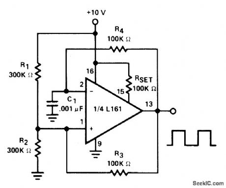
OSCILLATOR_CLOCK_GENERATOR
Published:2009/7/6 21:04:00 Author:May

This self-starting fixed-frequency oscillator circuit gives excellent frequency stability. R1 and C1 comprise the frequency-determining network, while R2 provides the regenerative feedback.Diode D1 enhances the stability by compensating for the difference between VOH and VSUPPLY. In applications where a precision clock generator up to 100 kHz is required, such as in automatic test equipment, C1 might be replaced by a crystal. (View)
View full Circuit Diagram | Comments | Reading(1527)
TWO_STATE_NEON_OSCILLATOR
Published:2009/7/6 9:02:00 Author:May
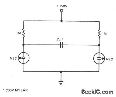
The number of lamps is easily increased in this oscillator. (View)
View full Circuit Diagram | Comments | Reading(646)
BASIC_MOS_OSCILLATOR
Published:2009/7/6 7:57:00 Author:May
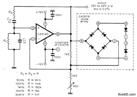
Output is 50 Hz when R1 and R2 are 3.3 megohms, increasing to 30 kHz as resistor values are reduced to 5100 ohms. Circuit has no inherent lower frequency limit; with 22-megohm resistors and 1-μF capacitors for C1 and C2, sine-wave output is 0.007 Hz. Articlegives basic equations for circuit. Features indude high input impedance, fast slew rate, and high output voltage capability. Combination of bridge rectifier with monolithic zener diodes in regulating system provides practically zero temperature coefficient.-M. Bailey, Op-Amp Wien Bridge Oscillator, Wire-less World, Jan. 1977, p 77. (View)
View full Circuit Diagram | Comments | Reading(761)
15_57_MHz_OPTICALLY_ISOLATED_VFO
Published:2009/7/6 7:46:00 Author:May
View full Circuit Diagram | Comments | Reading(789)
SQUARE_WAVE_OSCILLATOR
Published:2009/7/6 7:24:00 Author:May
View full Circuit Diagram | Comments | Reading(0)
DC_DC_OPTOISOLATOR
Published:2009/7/6 7:14:00 Author:May
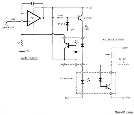
Designed to provide input isolation for thyristor converters. Linearity is within 2%. Loop gain of opamp makes diode turn-on voltage insignificant.-R. J. Haney, Linear D.C./D.C. Opto Isolator, Wireless World, June 1976, p 72. (View)
View full Circuit Diagram | Comments | Reading(1101)
LOW_FREQUENCY_TTL_OSCILLSATOR
Published:2009/7/6 7:11:00 Author:May
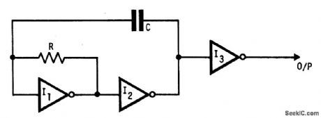
This oscillator uses standard inverters,one resistor and one capacitor,and has nommmlum operating frequency.R and C must be chosen such that currents into the gatesare below recommended operating limits and that leakage current into the gates andinto C are small h companson with the current in R also the output should be buffered(I3)to prevent variations h load affecting frequency.This circuit may also be used to square up slowly changing logic levels by use of multi input gates (NANDS,NORS Etc). (View)
View full Circuit Diagram | Comments | Reading(686)
LASCR_CONTROLLED_OSCILLATOR
Published:2009/7/6 6:15:00 Author:May
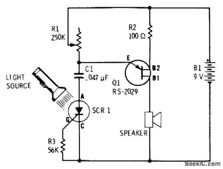
UJT relaxation oscillator having loudspeaker load produces single click each time flash of light falls on light-activated SCR Setting of R1 determines whether circuit produces series of pulses or tone burst during time light is on Oscillator frequency Increases with light intensity.-F. M. Mims, Semiconductor Proiects, Vol.2, RadioShack, Fort Worth, TX, 1976, p 71-77. (View)
View full Circuit Diagram | Comments | Reading(1741)
SOLAR_POWER_OSCILLATOR
Published:2009/7/6 6:14:00 Author:May
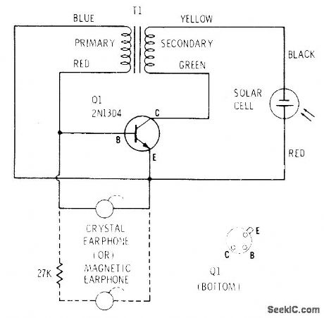
Supply voltage for single-transistor audio oscillator is generated by Radio Shack 276-115 selenium solar cell that produces about 0.35 V in bright sunlight. With cell 3 feet away from 75-W incandescent lamp, oscillator frequency is about 2400 Hz. Frequency drops as light increases. Transformer is 273-1378.-F. M. Mims, Transistor Projects, Vol. 2, Radio Shack, Fort Worth, TX, 1974, p 53-58. (View)
View full Circuit Diagram | Comments | Reading(1063)
5_kHz_PHOTOCELL_OSCILLATOR
Published:2009/7/6 6:04:00 Author:May
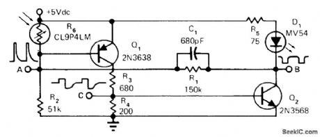
Provides 5-V pulses at about 5 kHz only if photocell is illuminated by its companion LED. Repetition rate varies with illumination, so interruption or attenuation of light produces easily detected frequency change that can be used as control signal. Applications include fail-safe interruption monitor and illumination transducer. Oscillation stops if beam is completely interrupted or if strong ambient light falls on photocell.-H. L. Hardy, FM Pulsed Photocell Is Foolproof, EDN Magazine, March 5, 1975, p 72. (View)
View full Circuit Diagram | Comments | Reading(786)
YELP_OSCILLATOR
Published:2009/7/6 5:44:00 Author:May


Close the pushbutton switch and the circuit starts the siren up-shifting to a higher frequency. Release it and the tone slides down until S2 is closed again. Tone quality is adjusted by changing the 0.022 μF capacitor.
(View)
View full Circuit Diagram | Comments | Reading(822)
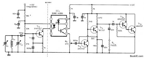
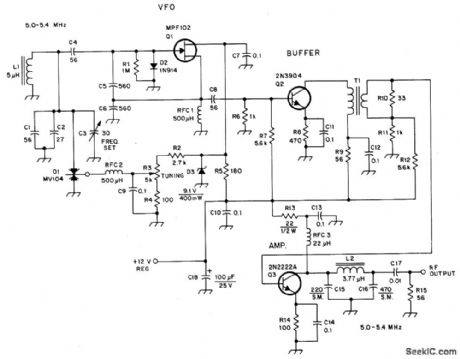
5_MHz_VFO
Published:2009/7/6 5:23:00 Author:May
Circuit Notes
AJFET (Q1) serves as the oscillator. D2 helps to stabilize the transistor by limiting positive sinewave peaks and stabilizing the bias. Output from Q1 is supplied to a class A buffer, Q2. It operates as a broadband amplifter by means of T1, which is untuned. Output amplifter Q3 is also a class A stage. A low-pass, single-section ftlter is used at the output of Q3 to remove some of the harmonic currents generated within the system.The ftlter output impedance is 50 ohms. The injection level to the mixer is 600 mV p-p. (View)
View full Circuit Diagram | Comments | Reading(1153)
100_MHz_CRYSTAL_OSCILLATOR
Published:2009/7/6 2:44:00 Author:May
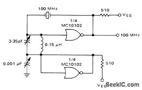
Developed for frequency counter that uses standard ECL components. Crystal can be changed to 10 MHz when measuring TTL performance.-W. B.Blood, Jr., Measure Frequency and Propagation Delay whh High Speed MECL Circuits, Motorola, Phoenix, AZ, 1972, AN-586 p 3.
(View)
View full Circuit Diagram | Comments | Reading(89)
SWITCHED_OVERTONE_CRYSTALS
Published:2009/7/6 0:57:00 Author:May

Uses third-overtone crystals between 20 and 80 MHz, with diode switching and with frequency doubling in transistors. L1-Ln ate series resonant with 10 pF at each crystal frequency. L4 is resonant with l0 pF at desired output frequency. L3 and L5 have one-third as many turns as L4. Q1 is 2N918, BF115, HEP709, or equivalent. Diodes are switching types such as BAY67.-U. Rohde, Stable Crystal Oscillators, Ham Radio, June 1975, p 34-37. (View)
View full Circuit Diagram | Comments | Reading(1101)
1_kHz_V_FOR_VCO
Published:2009/7/6 0:55:00 Author:May

Voltage-contronea oscillator uses CA3130 opamp as MVBR and CA3160 opamp as comparator. Tracking error is about 0.02%, and temperature coefficient is 0.01% per degree C.- Circuit Ideas for RCA Linear ICs, RCA Solid State Division, Somerville, NJ, 1977, p4. (View)
View full Circuit Diagram | Comments | Reading(850)
STABLE_35_38_MHz_VFO
Published:2009/7/6 0:54:00 Author:May

Oscillator Q1-Q2, emitter-follower output Q3, and buffer Q4 provide 5 V P-P into 200-ohm load, with good isolation between oscillator and load Total drift is less than 10 Hz from turn-on, and less than 330 Hz as supply voltage varies between 15 and 30 V. Amplitude stability is within 1 dB over tuning range. Oscillator amplitude is stabilized by two 1N34 diodes and 3.3-V zener. L1 is 25 turns No. 18 closewound on 1.5-in form. –J. Fisk, Circuit sand Techniques, Ham Radio, June 1976, p 48-52. (View)
View full Circuit Diagram | Comments | Reading(888)
160_METER_VFO
Published:2009/7/6 0:52:00 Author:May

Standard Colpitts oscillator Q1 with emitter-follower Q2 gives dependability and adequate isolation from later stages Zener regulation provides stability even with weak battery Output is about 0.7 VRMS. Low-level parasitic oscillation may occur about 150 kHz below operating frequency but is suppressed by tuned stages following VFO. L1 is 52 turns No. 28 enamel on Amidon T-50-2 toroid. RFC1 is 850μH.-A Weiss, Design Notes on a Moderate Power Solid State Transmitter for 1.8 MHz, CQ, Nov. 1972, p 18-22, 24, 98, 100, and 102. (View)
View full Circuit Diagram | Comments | Reading(1771)
3_20_MHz_CRYSTAL
Published:2009/7/6 0:51:00 Author:May

Circuit is series-mode oscillator, but parallel-mode crystals can be used if trimmer in series with crystal is replaced by short-circuit. Adjust feedback by varying ratio of C1 to C2. Use grid-dip oscillator to resonate L1 with C1 when crystal is shorted; then remove short and tune slug of L1 to pull crystal exactly to frequency. R1 should be between 100 and 1000 ohms. The lower its value, the lower the crystal power dissipation and the better is stability. Q1 is 2N918, 2N3564, 2N5770, BF200, SE1001, or equivalent.-R. Harrison, Survey of Crystal Oscillators, Ham Radio, March 1976, p 10-22. (View)
View full Circuit Diagram | Comments | Reading(2247)
| Pages:34/54 At 202122232425262728293031323334353637383940Under 20 |
Circuit Categories
power supply circuit
Amplifier Circuit
Basic Circuit
LED and Light Circuit
Sensor Circuit
Signal Processing
Electrical Equipment Circuit
Control Circuit
Remote Control Circuit
A/D-D/A Converter Circuit
Audio Circuit
Measuring and Test Circuit
Communication Circuit
Computer-Related Circuit
555 Circuit
Automotive Circuit
Repairing Circuit