
Index 83
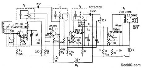
TUNER_FOR_A_M_F_M_PORTABLE
Published:2009/7/19 23:21:00 Author:Jessie

R-f amplifier Q1, mixer Q2, and local oscillator Q3 are all switched to perform same functions on f-m as on aim. Grounded-base oscillator Q3 requires careful design to compensate for transconductance phase shift at highest frequency of oscillation (118.7 Mc), Overall gain of tuner is 25.5 db at 88 Mc and 22.5 db at 108 Mc.-R. A. Santilli and H. Thanos, Portable Radio Uses Drift-Field Transistors, Electronics, 33:28, p 48-50. (View)
View full Circuit Diagram | Comments | Reading(509)
24_MC_CLAPP_1
Published:2009/7/19 23:20:00 Author:Jessie

Delivers 300 mw into 50-ohm load. Typical collector efficiency is 35%. -Texas Instruments Inc., Solid-State Communications, McGraw-Hill, N.Y., 1966, p 239. (View)
View full Circuit Diagram | Comments | Reading(559)
RF_oscillator_
Published:2009/7/19 23:20:00 Author:Jessie


This circuit uses the LM3909 as a low-power RF oscillator (chapter 5). The tuned circuit is a standard AM-radio ferrite antenna coil (loopstick) with a tap 40% of the turns up from one end. The tuning capacitor is a standard 360-pF AM-radio tuning capacitor The high-frequency limit is about 800 kHz. (View)
View full Circuit Diagram | Comments | Reading(1059)
DELAY_LINE_OSCILLATOR
Published:2009/7/19 23:19:00 Author:Jessie
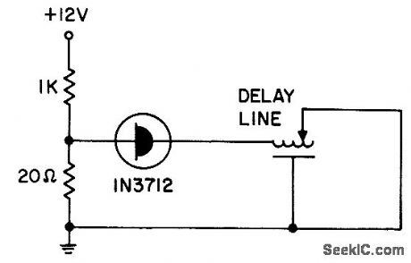
Tunnel-diode oscillator with General Radio 314-586 delay line produces square-wave output in range of 0.5 to 20 Mc.- Transistor Manual, Seventh Edition, General Electric Co., 1964, p 352. (View)
View full Circuit Diagram | Comments | Reading(1335)
9_KC_INDUCTION_RECEIVER
Published:2009/7/19 23:18:00 Author:Jessie
Thermistor network in base circuits of transistors provide thermal compensation between -30 and +140°F, for picking up messages broadcast from roadside telephone-line loops.-E. A. Hanysz, J. E. Stevens, and A. Meduvsky, Communication System for Highway Traffic Control, Electronics, 33:42, p 81-83. (View)
View full Circuit Diagram | Comments | Reading(645)
PREFERRED_2000_83000_PPS_BLOCKING_OSCILLATOR
Published:2009/7/19 23:18:00 Author:Jessie

Parallel-triggered circuit responds to trigger pulses separated by only few microsec, as required for distance-mark generators and pulse coding circuits. Input is positive, with minimum of 15 V, and output is positive. R6 is 220 ohms. R7 is maximum that will just suppress ringing.-NBS, Handbook Preferred Circuits Navy Aeronautical Electronic Equipment, Vol. I, Electron Tube Circuits, 1963, PC 47, p 47-2. (View)
View full Circuit Diagram | Comments | Reading(634)
200_400_Mc_VARICAP_TUNED_OSCILLATOR_
Published:2009/7/19 23:15:00 Author:Jessie

Tuning range is achieved by adjusting Voricap bias voltage from 0.4 to 60 V.-E. Gottlieb and J. Giorgis, Tunnel Diodes-Using Them as Sinusoidal Generators, Electronics, 36:24, p 36-42. (View)
View full Circuit Diagram | Comments | Reading(600)
SSB_PRODUCT_DETECTOR
Published:2009/7/19 23:27:00 Author:Jessie
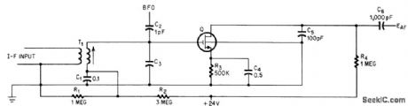
Square-law relationship between transconductance and drain current makes mos fet ideal for product detector in ssb receivers.-G. G. Luettgenau and S.H. Branes, Designing With Low-Noise MOS FETs: A Little Different But No Harder, Electronics, 37:31, p 53-58. (View)
View full Circuit Diagram | Comments | Reading(1009)
ELECTRIC_TUNING_FOR_600_to_1200_MC
Published:2009/7/19 23:27:00 Author:Jessie

Lumped-constant technique is used with voltage-tunable ferroelectric capacitors to provide 10 mw into 50 ohms.-T. W. Buller, Jr., Ferroelectrics Tune Electronic circuits, Electronics, 32;3, p 52-55. (View)
View full Circuit Diagram | Comments | Reading(576)
SIMPLE_TRANSISTOR_OSCILLATOR
Published:2009/7/19 23:26:00 Author:Jessie

Current gain is stabilized against transistor variation. Can be used over collector voltage range of 2 to 24 V. Oscillation occurs at frequency at which there is 360° total phase shift, 180° of which is furnished by grounded-emitter amplifier and 180° by high-pass network. 5K pot adjusts frequency from about 200 to 400 cps.- Tansistor Manual, Seventh Edition, General Electric Co., 1964, p 206. (View)
View full Circuit Diagram | Comments | Reading(1031)
CHATTER_JAMMER
Published:2009/7/19 23:14:00 Author:Jessie

Can be used to create pleasing tone at level that drowns out ambient noises, to permit concentration on problem while others are talking in vicinity.-J. Leeb, A Chatter Jammer Circuit, EEE, 10:11, p 31. (View)
View full Circuit Diagram | Comments | Reading(665)
LOAD_ISOLATING_3_35_MC_OSCILLATOR
Published:2009/7/19 23:13:00 Author:Jessie
Refined version of Lampkin variable r-f oscillator for dual-conversion receiver gives uniform output over band and sufficient stability for single-sideband reception after 30-see warmup.-E. Robberson, R-F Oscillator has improved Stability, Electronics, 36:32, p 62-63. (View)
View full Circuit Diagram | Comments | Reading(568)
TONE_BURST_OSCILLATOR
Published:2009/7/19 23:12:00 Author:Jessie
Consists of variable-frequency magnetically coupled mvbr, with two magnetic cores driven by battery-powered transistors. Injection of current or voltage from solar cell or other transducer affects mvbr reset, to give frequency change over range of 5 to 15 kc.-R. W. Rochelle, Cyclops Cores Simplify Earth-Satellite Circuits, Electronics, 31:9, 56-63. (View)
View full Circuit Diagram | Comments | Reading(654)
FOUR_TRANSISTOR_REFLEX_PORTABLE
Published:2009/7/19 23:11:00 Author:Jessie
Second if stage doubles as audio amplifier to give five-stage performance.-E. Gottlieb, Transistor Reflex Circuit Trims Receiver Costs, Electronics, 31:1, p 66-68. (View)
View full Circuit Diagram | Comments | Reading(766)
STABLE_OSCILLATOR
Published:2009/7/19 23:09:00 Author:Jessie

Excellent frequency and amplitude stability is accomplished by eliminating all grid current in tank circuit and by isolating tank from driving tube by means of resistive degeneration. If very pure sine wove is required, grid of V1 should be coupled to high-impedance load that is equivalent constant resistance, because either reacyive or variable loads will impair stability.-J. C. Davis, Stable Oscillator Circuit, EEE, 11:2, p 26. (View)
View full Circuit Diagram | Comments | Reading(819)
FOUR_LAYER_DIODE_OSCILLATOR
Published:2009/7/19 23:07:00 Author:Jessie

If circuit is broken at X, discharge current of C1 can be used to shut off transistor stage.-A. G. Lloyd, Overload Protection for Transistor Voltage Regulators, Electronics, 33:52, p 56-59. (View)
View full Circuit Diagram | Comments | Reading(646)
VOLTAGE_TUNABLE_CARCINOTRON_CONTROL
Published:2009/7/19 23:07:00 Author:Jessie
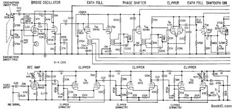
Used with superheterodyne receiver to provide continuous frequency coverage from 30 Mc to 75,000 Mc by means of harmonic mixing.-C. H. Currie, Carcinotron Harmonics -. Boost Receiver Range, Electronics, 32:9, p 58-61. (View)
View full Circuit Diagram | Comments | Reading(581)
FM_tuning_indicator_circuit_using_an_ECG1149_14_pin_DIP
Published:2009/7/19 23:05:00 Author:Jessie
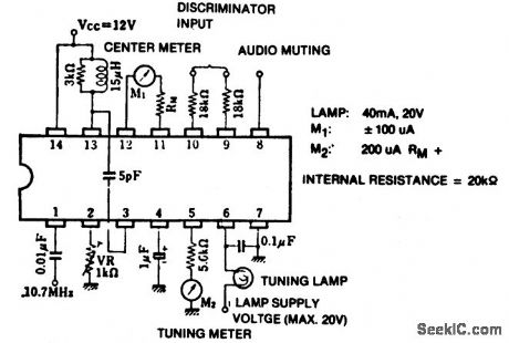
FM tuning indicator circuit using an ECG1149 14-pin DIP.Recommended supply voltage is 12 volts.Lamp turn-on voltage at 10.7 MHz is 10 mV(courtesy GTE Sylvania Incorporated). (View)
View full Circuit Diagram | Comments | Reading(1032)
FM_IF_amplifier_for_FM_broadcast_receiver
Published:2009/7/19 23:04:00 Author:Jessie
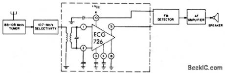
FM IF amplifier for FM broadcast receiver.Supply voltage can be between 6 and 12 volts,the typical being 7.5 volts,Voltage gainis between 55 and 67 dB,depending on the IF(courtesy GTE Sylvania Incorporated). (View)
View full Circuit Diagram | Comments | Reading(475)
THREE_STAGE_VARIABLE_FREQUENCY_CRYSTAL_OSCILLATOR
Published:2009/7/19 23:03:00 Author:Jessie
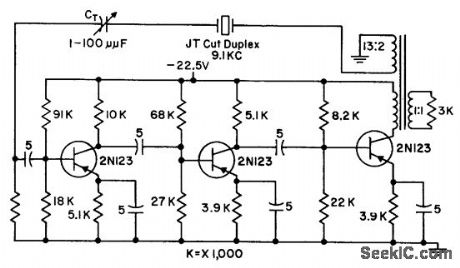
Provides loop transmission of 1, under maximum frequency pulloff of 5 cps from 9.1-kc crystal frequency, and has net phase shift around loop of 360°with crystal in circuit. Third stage provides extra circuit gain needed for larger power output or larger frequency deviations off resonance. Transformer provides phase reversal and reflects desired a-c load, to limit output swing of transistor.-G. A. Gedney and G. M. Davidson, Crystal Oscillator has Variable Frequency, Electronics, 31:7, p 118-119. (View)
View full Circuit Diagram | Comments | Reading(778)
| Pages:83/195 At 2081828384858687888990919293949596979899100Under 20 |
Circuit Categories
power supply circuit
Amplifier Circuit
Basic Circuit
LED and Light Circuit
Sensor Circuit
Signal Processing
Electrical Equipment Circuit
Control Circuit
Remote Control Circuit
A/D-D/A Converter Circuit
Audio Circuit
Measuring and Test Circuit
Communication Circuit
Computer-Related Circuit
555 Circuit
Automotive Circuit
Repairing Circuit