
Index 245
The application circuit of pulse width modulated type switching stabilized voltage supply
Published:2011/4/19 4:00:00 Author:May | Keyword: pulse width modulated, switching, stabilized voltage supply

In the diagram it is an actual example of pulse width modulated switching regulated power supply. It is Kaige 4D17U type which is produced by Shanghai the fourth radio factory. It is stabilized voltage supply of 35cm black and white TV set.
Its main technical target is shown in the following:
Output voltage: 12V;
Output current: 1A’
Power consumption <20W;
Efficiency >64%
Internal resistance <0.075Ω;
Ripples <15mV;
Commercial power voltage: 160~240V.
In the diagram, full wave rectification circuit consists of 6VD1, 6VD2; 6C3 is filter capacitor; 6C1, 6C2 is used to slack down surge current; free running multi-vibrator consists of 6VT7, 6VT2, 6VT3 and 6VT4, 6C9. At the same time, 6VT7 is switching tube.
When 12V output voltage reduced because of some reasons, the voltage which is got from sample circuit 6R6, 6R9, and 6R8 by error amplifier tube 6VT5 is also reducing. 6VT5’s collector voltage is rising. 6VT3’s base level is rising too. The output pulse of 6VT7 is broadening. Then the reduced voltage is rising again. On the contrary, when output voltage reduced, we can opposite adjust according to this process above mentioned. It can let the output voltage remain stable. (View)
View full Circuit Diagram | Comments | Reading(1621)
Novel neon-electroscope circuit
Published:2011/4/13 4:21:00 Author:Nicole | Keyword: neon-electroscope

When measuring municipal electric power, the weak current flowsresistance and neon tube, making the neon tube luminescence, and the oscillation circuit composed of CMOS IC starts to oscillate, piezoceramics produces a sound. (View)
View full Circuit Diagram | Comments | Reading(1045)
Serial voltage stabilizing circuit with few residual Voltage
Published:2011/4/13 4:13:00 Author:Nicole | Keyword: voltage stabilizing, few residual voltage

This circuit uses the collector of serial transistor as output terminal, the minimum voltage difference between lowest roll in voltage and steady output voltage can reach 1.2V. Adopting two regulator tubes can ensure the output voltage with high stability. Using 2.5kΩ potentiometer can set output voltage to the given value. 1nF capacitance can suppress high frequency oscillation. (View)
View full Circuit Diagram | Comments | Reading(515)
Larger current steady voltage circuit with current limit
Published:2011/4/17 8:07:00 Author:Nicole | Keyword: larger current, steady voltage, current limit

In figure, the choice of resistances R1 and R2 should meet the condition of R2≧5*R1. Such as R1=0.2Ω, R2=1Ω. In practice, according to the current, R1 should be between 0.1~2Ω, because of UBE=UD, then UR1=UR2, so I2 is lower than 5 times of I3, total current I1=I2+I3≈I4, neglecting the base current of transistor, then I3 is equal to the adjustment current of integrated circuit IC. For large current transistor, the resistance R3 can be selected between 10~20Ω. For small current transistor, the resistance can be choiced of 100Ω. (View)
View full Circuit Diagram | Comments | Reading(502)
A kind of full automatic charger circuit
Published:2011/4/19 4:25:00 Author:May | Keyword: full automatic charger

working principleDiagram 4-27 is the principle diagram of this charger. The voltage of LM339's pin 5 V5=6V. When the battery voltage E is less than 12V, V4 is less than 6V. LM339's pin 2 outputs high level. It can let 9013 saturation. 3AD30 is on amplified state. The measured value is 300mA when using heavy current to charge. When E≥12V, V5≥6V. LM339's pin 2 output low level. 9013 and 3AD30 is cut off. It adopts 40mA low current to charge to the battery. The curved line of measured charge current is shown in diagram 4-28.
(View)
View full Circuit Diagram | Comments | Reading(1652)
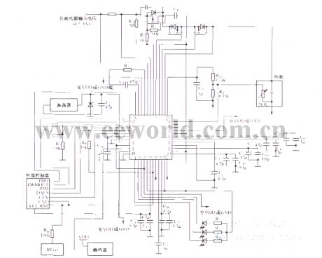
Hisense TC2102GD TV switching power supply (MC44608P75) circuit diagram
Published:2011/4/20 9:06:00 Author:Nicole | Keyword: Hisense, TV Power Supply

View full Circuit Diagram | Comments | Reading(3163)
Hisense ITV2911 TV switching power supply (KA3S0680R) circuit diagram
Published:2011/4/20 9:06:00 Author:Nicole | Keyword: Hisense, TV Power Supply

View full Circuit Diagram | Comments | Reading(3775)
Based on staple Changhong PF2991E Large-screen flat screen color TV switching power supply circuit diagram
Published:2011/4/20 9:07:00 Author:Nicole | Keyword: Changhong, TV Power Supply

View full Circuit Diagram | Comments | Reading(3186)
Konka P2592N Mirror TV switching power supply (DTR-S6709A) circuit diagram
Published:2011/4/20 9:06:00 Author:Nicole | Keyword: Konka, TV Power Supply

View full Circuit Diagram | Comments | Reading(3030)
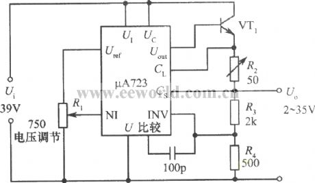
2~35V、10A adjustable regulated power supply with μA723
Published:2011/4/20 4:39:00 Author:Nicole | Keyword: regulated power supply
View full Circuit Diagram | Comments | Reading(1006)
TWL2213 typical application circuit charge circuit
Published:2011/4/20 8:08:00 Author:Nicole | Keyword: typical application, charge
The related components information applied in this circuit: TWL2213 is mainly used in power management of portable instruments or equipments which is powered by lithium ion battery such as PAD, telephone, pager. It is also designed for charging to lithium ion battery. The typical circuit is as below:
(View)
View full Circuit Diagram | Comments | Reading(568)
TWL2213 pin arrangement diagram
Published:2011/4/20 7:52:00 Author:Nicole | Keyword: pin
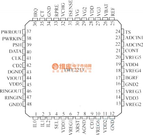
TWL2213 is produced by US TI Company, it is a new type power management and lithium ion battery charge control IC, it is designed for portable IT products. (View)
View full Circuit Diagram | Comments | Reading(534)
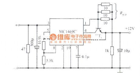
High stable 12V regulated power supply composed of MC1469C integrated regulator
Published:2011/4/20 4:42:00 Author:Nicole | Keyword: 12V regulated power supply, integrated regulator
View full Circuit Diagram | Comments | Reading(700)
Single-ended forward converter circuit diagram
Published:2011/3/30 3:28:00 Author:Nicole | Keyword: converter
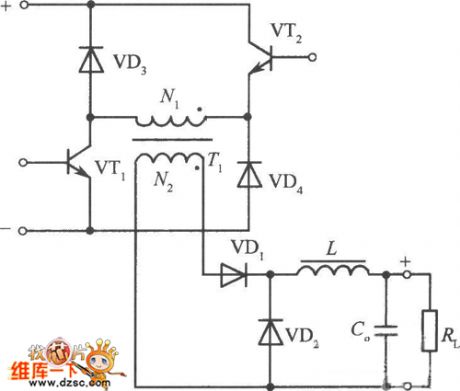
The figure is a single-ended forward converter circuit composed of two transistors, diode clamped. VTl and VT2 is on/offsimultaneously by PWM pulse excitation. When they off, the voltage on N1 is polarity reversed, diodes VD3 and VD4 on, the potentialis clamped. Therefore, the voltage which is added to collector is equal to the input voltage Ui during the VTl, VT2 off.
(View)
View full Circuit Diagram | Comments | Reading(875)
Single-ended flyback switching power supply circuit diagram
Published:2011/4/1 3:50:00 Author:Nicole | Keyword: single-ended switching power supply

View full Circuit Diagram | Comments | Reading(746)
Protecting circuit diagram of ring switch on
Published:2011/4/1 3:51:00 Author:Nicole | Keyword: ring switch

View full Circuit Diagram | Comments | Reading(686)
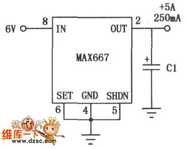
Application circuit diagram of MAX667 multifunction linear integrated regulator with high-precision
Published:2011/4/1 3:57:00 Author:Nicole | Keyword: linear integrated regulator
View full Circuit Diagram | Comments | Reading(543)
MAX639 series multi-function integrated switching regulator circuit diagram of fixed / adjustable output
Published:2011/4/1 3:58:00 Author:Nicole | Keyword: integrated switching regulator

MAX639 series fixed / adjustable output multi-function integrated switching regulator circuit is an efficient, multi-function switching regulator circuit, the output voltage is +5 v, the input voltage is 5.5 ~ 11.5V, output current is 100mA. It is efficient, the electronic switch control terminal of the logic level control and the battery-side low-voltage detectionare havethe advantages of low-power, low dropout, multi-functional, it is widely used in portable instruments, meters and so on. The basic application as shown. The typical application circuit of voltage detection can be see as below.
(View)
View full Circuit Diagram | Comments | Reading(1724)
Application circuit diagram of switching regulator with input l0 ~ 15V / Output 5V/3A
Published:2011/4/1 3:32:00 Author:Nicole | Keyword: switching regulator

View full Circuit Diagram | Comments | Reading(878)
Application circuit diagram of output voltage circuit can be connected into two kinds
Published:2011/4/1 3:31:00 Author:Nicole | Keyword: output voltage circuit
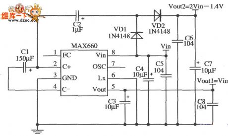
MAX660 can be connected into two kinds of output voltage circuit: Voutl=Vin;Vout2=2Vin-1.4 V. Output resistance of this circuit is slightly larger, as shown.
(View)
View full Circuit Diagram | Comments | Reading(576)
| Pages:245/291 At 20241242243244245246247248249250251252253254255256257258259260Under 20 |
Circuit Categories
power supply circuit
Amplifier Circuit
Basic Circuit
LED and Light Circuit
Sensor Circuit
Signal Processing
Electrical Equipment Circuit
Control Circuit
Remote Control Circuit
A/D-D/A Converter Circuit
Audio Circuit
Measuring and Test Circuit
Communication Circuit
Computer-Related Circuit
555 Circuit
Automotive Circuit
Repairing Circuit