Position: Home > Circuit Diagram > power supply circuit > Single-ended forward converter circuit diagram
power supply circuit
Single-ended forward converter circuit diagram
Published:2011/3/30 3:28:00 Author:Nicole | Keyword: converter | From:SeekIC

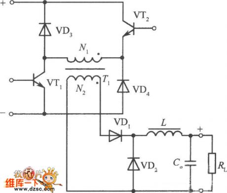
The figure is a single-ended forward converter circuit composed of two transistors, diode clamped. VTl and VT2 is on/offsimultaneously by PWM pulse excitation. When they off, the voltage on N1 is polarity reversed, diodes VD3 and VD4 on, the potentialis clamped. Therefore, the voltage which is added to collector is equal to the input voltage Ui during the VTl, VT2 off.
Reprinted Url Of This Article:
http://www.seekic.com/circuit_diagram/Power_Supply_Circuit/Single_ended_forward_converter_circuit_diagram.html
Print this Page | Comments | Reading(3)

Article Categories
power supply circuit
Amplifier Circuit
Basic Circuit
LED and Light Circuit
Sensor Circuit
Signal Processing
Electrical Equipment Circuit
Control Circuit
Remote Control Circuit
A/D-D/A Converter Circuit
Audio Circuit
Measuring and Test Circuit
Communication Circuit
Computer-Related Circuit
555 Circuit
Automotive Circuit
Repairing Circuit
Code: