
Power-Supply Circuits-Fixed
Index 4
Numerical Control D. C. Regulated Power Supply Eight
Published:2011/6/2 11:07:00 Author:Michel | Keyword: Numerical Control, D. C., Regulated Power Supply, Eight
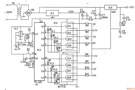

The numerical control D. C. power-supply circuits-fixed introduced in the example uses control buttons and digital IC and it adopts LED to indicate the magnitude of the output voltage which has 8 grades.Its maximum current is 1.5A.
Work's Principle of the CircuitThe numerical control D. C. power-supply circuits-fixed is composed of +12V voltage constant voltage control circuit,voltage control indication circuit and constant voltage output circuit and it is showed as the 5-27 picture.
The +12V voltage constant voltage control circuit consists of mains transformer,T,rectifier bridge,UR,filter capacitor,C1,C2,C6,C7 and three-terminal integrated regulator,IC1. (View)
View full Circuit Diagram | Comments | Reading(1212)
Numerical Control D. C. Regulated Power Supply Seven
Published:2011/6/2 11:03:00 Author:Michel | Keyword: Numerical Control, D. C., Regulated Power Supply, Seven
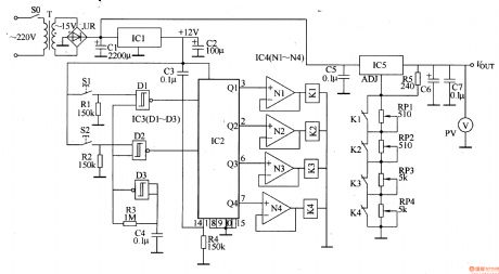
The numerical control D. C. power-supply circuits-fixed introduced in the example uses digital IC to control the power-supply circuits-fixed and the user adopts two buttons to regulate the magnitude of the voltage conveniently.
Work's Principle of the Circuit
The numerical control D. C. power-supply circuits-fixed consists of +12V voltage constant voltage control circuit,voltage control circuit and constant voltage output circuit and it is showed as the 5-26 picture.+12Vvoltage constant voltage control circuit is composed of mains switch,SO,mains transformer,T,rectifier bridge,UR,filter capacitor,C1-C3 and three-terminal integrated regulator,IC1. (View)
View full Circuit Diagram | Comments | Reading(888)
Numerical Control D. C. Regulated Power Supply Five
Published:2011/6/2 10:58:00 Author:Michel | Keyword: Numerical Control, D. C., Regulated Power Supply, Five

The numerical control D. C. power-supply circuits-fixed introduced in the example uses control button to choose output voltage (range:1.5-15V)and adopts LED to indicate the magnitude of voltage,which is convenient and intuitionistic.
Work's Principle of the Circuit
The numerical control D. C. power-supply circuits-fixed is omposed of power-supply circuits-fixed and ouput voltage control circuitand it is showed as the picture 5-24.
The power-supply circuits-fixed consists of mains switch,S1,mains tranformer,T,rectifier bridge,UR,capacitor,C1-C3,three-terminal integrated regulator,IC1and IC2 and resistor,RO-R1O. (View)
View full Circuit Diagram | Comments | Reading(1070)
AC Voltage Regulator Thirteen
Published:2011/6/3 8:33:00 Author:Michel | Keyword: AC, Voltage Regulator, Thirteen

The AC voltage regulator introduced in the example uses servo-type control circuit.It has good dependability and wide adjustable range.
Circuit's Wrok Principle
The circuit is composed of voltage stabilizing circuit,voltage test control circuit and voltage regulation output circuit and it is showed as the picture 5-52.The voltage stabilizing circuit consists of self-coupling transformer,T,communication diode VD1-VD4,filter capacitor CT,current-limitting resistor R1,R2 and voltage regulation diode VS1,VS2.
The voltage test control circuit is composed of R3-R9,diode VD5,VD6,LED VL,relay K1,K2,potentiometer RP,transistor V1,V2 and operational amplifier IC(N1,N2). (View)
View full Circuit Diagram | Comments | Reading(2827)
Numerical Control D. C. Regulated Power Supply Fifteen
Published:2011/6/2 12:07:00 Author:Michel | Keyword: Numerical Control, D. C., Regulated Power Supply, Fifteen

The numerical control D. C. power-supply circuits-fixed introduced in the example uses metal touch button ,digital IC and electron switch IC to converse the magnitude of output voltage.Compared to D. C. regualted power-supply cf traditional mechnical range switch,it has the advantage of lowbreakdown and convenient operation.
Work's Principle of the Circuit
The numerical control D. C. power-supply circuits-fixed is composed of mains circuit,free-running multivibrator,counting distributor,analog switching circuit and control circuit and it is showed as the picture 5-34.The mains circuit consists of mains transformer,T,rectifier bridge,UR,capacitor,C1-C5,resistor,R9,R10,diode,VD1,VD2,three-terminal integrated regulator,IC1 and zener diode,VS. (View)
View full Circuit Diagram | Comments | Reading(1964)
AC Voltage Regulator Twelve
Published:2011/6/3 6:54:00 Author:Michel | Keyword: AC, Voltage Regulator, Twelve

The AC voltage regulator uses servo-type control circuit which has wide voltage regulation range(The input AC voltage range is 160-260V)and high control accuracy.This circuit is easy to make and suitable for where the utility power is unstable.
Circuit's Work Principle
The AC voltage regulator circuit is composed of 士l2V mains circuirt ,voltage test circuit and overvoltage protection circuit and it is showed as the picture 5-51.The 士l2V power supply circuit consists of powerstat,W4 and W5,commutation diode,VD1-VD4 and filter capacitor C1 and C2. (View)
View full Circuit Diagram | Comments | Reading(2522)
AC Voltage Regulator Eleven
Published:2011/6/3 7:47:00 Author:Michel | Keyword: AC, Voltage Regulator, Eleven

This example introduces an AC regulator composed of electronic switching IC and thyristor etc.Comparedwith the AC voltage regulator whose voltage converts by relay,it has no mechnical converting noises and momentary breakdown with long performance life.The regualtor can make sure the output voltage is 220V士l0V when the input AC voltage alters between 160-250V.
Circuit's Wrok Principle
The regulator circuit consists of four groups of stabilized voltage control circuit and it is showed as the picture 5-50.The first group stabilized voltage control circuit is composed of thyristor VT1,VT2,diode VD1,rectifier bridge UR1,resistor R1-R4, potentiometer RP1,capacitor C1,C2,electronic switching Intergrated Circuit IC1,transistor V1 and transformer group's W1 and W2. (View)
View full Circuit Diagram | Comments | Reading(1064)
AC Voltage Regulator Ten
Published:2011/5/22 1:25:00 Author:Michel | Keyword: AC Voltage Regulator, Ten

The AC voltage regulator introudced in the example has the features of broad voltage regulation range(102-262V),perfect protection effects(powerdown delay electrification,380V phase dislocation-proofing and lightning protection and statics-proofing etc.) and high sensitivity and it's available in families with unsable line voltage.
Circuit's WorkPrincipleThe AC voltage regulatorcircuit is composed of +5V voltage regulation circuit,voltage test circuit,control circuit,protection circuit and voltage regualation output circuit and it is showed as the picture 5-49.The +5V voltage regulation circuit consists of fuse,FU1-FU3,autotransformer,T,commutation diode,VD1,filter capacitor,C1,three-terminal voltage regulation IC,IC1,resistor,R21 andpowersupply indication LED,VL. (View)
View full Circuit Diagram | Comments | Reading(2468)
AC Voltage Regulator Nine
Published:2011/5/22 1:29:00 Author:Michel | Keyword: AC Voltage Regulator, Nine

The AC voltage regulator introudced in the example is made from 100-200W mains transformer and discrete components with simple circuits and material which can be used by the area's famlies whose line voltage is low(190-220V).
Circuit's Work Principle
The AC voltage regulator is composed of power supply circuit,voltage test control circuit and it is showed as the picture 5-48.The power supply circuitconsists of mains switch,S,fuse,FU,transformer,T,diode,VD2,capacitor,C1-C3,power suorce indication LED,VL2,resistor,R2 and R8 and voltage regulation diode,VS.
(View)
View full Circuit Diagram | Comments | Reading(1314)
AC Voltage Regulator Eight
Published:2011/5/22 1:13:00 Author:Michel | Keyword: AC Voltage Regulator, Eight

The automatic AC voltage regulatorintroduced in the example owns broad voltage regulation range,which can output 220V alternating voltage when the input alternating voltage is 110-380V so it's availabe for where the alternating voltage power supply is unstable.
Circuit's Work Principle
This AC voltage regulator circuit is composed of power supply circuit,voltage test control circuit and voltage regulation output circuit and it is showed as the picture 5-47.The power supply circuit consists of reduction voltage capacitor,C2,current-limiting resistor,R31and R33,commutation diode,VD44 and VD45,filter capacitor,C3 and C4,potentiometer,RP and voltage regulation diode,VS1. (View)
View full Circuit Diagram | Comments | Reading(1787)
AC Voltage Regulator Seven
Published:2011/5/22 1:10:00 Author:Michel | Keyword: AC Voltage Regulator, Seven

The AC voltage regulator introudced in the example has the functions of bootstrap power transmission delay,regulated output voltage,overvoltage and undertension's protection and indication and its output power is 3kW.
Circuit's Work PrincipleThe AC voltage regulator is composed of power supply circuit,lifting and reduction control circuit,bootstrap time delay circuit,overvoltage protection circuit and undertension protection circuit and it is showed as the picture 5-46.The power supply circuit consists of mains switch,S1, voltmeter,PV1,voltage-regulating transformer,T,rectifier bridge,UR2 and three-terminal voltage regulation IC,IC1,and filter capacitor,C1 and C2. (View)
View full Circuit Diagram | Comments | Reading(2531)
AC Voltage Regulator Six
Published:2011/5/22 1:08:00 Author:Michel | Keyword: AC Voltage Regulator, Six

The voltage AC regulator introduced in the example is controlled by SL322 LED driver IC.It can be used as automatic tap changer and voltage lighting indication where the commercial power often is low.
Circuit's Work Principle
The voltage AC regulator is composed of power supply circuit,voltage test control circuit and control operation circuit and it is showed as the picture 5-45.The power supply circuit consists of fuse,FU ,mains transformer,T,rectifier bridge,UR and filter capacitor,C1. (View)
View full Circuit Diagram | Comments | Reading(2624)
AC Voltage Regulator Five
Published:2011/6/3 5:02:00 Author:Michel | Keyword: AC Voltage Regulator, Five

The input and output voltage of the lifting voltage AC regulator introduced in the example are 150-230V and 220 (1土5%)V respectively.This regulator can be used by these families with unstabilized and low voltage.
Circuit's Work Principle
This AC regulator circuit is composed of power supply circuit,voltage test circuit and lifting voltage control circuit and it is showed as the picture 5-44.The power
supply circuit consists of mains switch,S,fuse,FU,mains transformer,T,commutation diode,VD1-VD4,filter,capacitor,C1 and C2 and three-termianl voltage control IC,IC. (View)
View full Circuit Diagram | Comments | Reading(2305)
AC Voltage Regulator Four
Published:2011/5/22 1:02:00 Author:Michel | Keyword: AC Voltage Regulator, Four

The input and output voltage range and output power range AC voltage regulator introudced in the example are 160-270V,220(1士5%)V and 600-800W respectively,which can meet the need of general household appliances.
Circuit's Work Principle
The AC voltage regulator circuit is composed of lifting and reduction voltage commutation circuits and automatic control circuit and it is showed as the picture 5-43.The lifting and reduction commutation circuits consists of power supply transformer's(T) Wl-W6 winding,relay's normally closed contact Kl-l-K5-1,normally open contact Kl-2-K5-2 and voltmeter,PV and it is showed as the picture. (View)
View full Circuit Diagram | Comments | Reading(4434)
AC Voltage Regulator Three
Published:2011/5/22 1:00:00 Author:Michel | Keyword: AC Voltage Regulator, Three

The AC voltage regulator introudced in the example has the functions of automatic voltage control and regulation.Its input voltage is from 120V to 260V,output voltage is 220V(11士10%)V and output power is from 300 to 1000W(It depends on transformer and relay contact terminal's current capacity).
Circuit's Work Principle
The AC voltage regulator circuit is composed of power supply circuit and voltage test circuit and it is showed as the picture 5-42.The power supply circuit consists of reduction voltage capacitor,C1 and C2,resistor,R1,commutation diode,VD1-VD4,filter capacitor,C3,voltage control diode,VS and transistor,transistor,V. (View)
View full Circuit Diagram | Comments | Reading(8483)
AC Voltage Regulator Two
Published:2011/5/22 0:57:00 Author:Michel | Keyword: AC Voltage Regulator, Two

The AC voltage regulator introudced in the example can control and regulate voltage automatically,cut off when it is idle load and voltage is over to save engery and protect the regulator.The regulator's input voltage range is from 65V to 250V,output voltage range is 195V to 230V and output power is 500W.
Circuit's Work Principle
The AC voltage regulator circuit is composed of power supply voltage control,voltage test,control circuit and time delay circuit and it is showed as the picture 5-41.The power supply voltage control consists of mains transformer,T,rectifier bridge,UR,filter capacitor,C6 and C7,three-terminal voltage control IC,IC2 and power indication LED,VL3 and current-limiting resistor,R14.
(View)
View full Circuit Diagram | Comments | Reading(4658)
Energy-efficient motorcycle regulating rectifier circuit
Published:2011/5/23 21:30:00 Author:John | Keyword: motorcycle regulating rectifier

Motorcycles are generally powered by magneto of the car. Output voltage of Magneto is regulated by regulating rectifier to supply electric appliances on the car and to charge the battery. At present, parallel switching regulating rectifier are widely used in many domestic motorcycles, just shown in Figure 1. The device takes effects when the output voltage of magneto is over the rated voltage. The device takes effects when the output voltage of magneto is over the rated voltage. The thyristor rectifier SCR1 and SCR2 inside of SCR rectifier voltage regulator opens to clip the output voltage of magneto, achieving the voltage regulation.
(View)
View full Circuit Diagram | Comments | Reading(5014)
4W switch-type 5V regulated DC power supply circuit
Published:2011/5/29 7:25:00 Author:chopper | Keyword: 4W, switch-type, 5V, regulated DC power supply

View full Circuit Diagram | Comments | Reading(1350)
power-supply circuits-fixed of numerical control and DC part 1
Published:2011/5/29 20:13:00 Author:Ariel Wang | Keyword: mumerical control, DC, circuits-fixed

After SI is being connected, 220VACvoltage is dropped down through T, commutated through UR and filtered through C1.It generates +18V DC voltage. The voltage is steady through IC2,IC3,IC4 and IC5. Then it generates the voltage of 5V,+6V,+9V and +l2V. These four groups are put on V1-V4 collectors. The voltage of +gV is being as working power supply as IC. After ICl electrified and reset, the YO edge(3 feet)is high power level output,Yl-Y9 is low power level output. Press S2,the CP edge (14 feet) will output a bigger counting pulse. The Yl egde wil output high power level,while YO edge turns back to low power level. Press S2 continuously,the YO-Y4 edge of ICl will output high power level one by one.
(View)
View full Circuit Diagram | Comments | Reading(945)
Logic control integrated regulated power supply circuit diagram
Published:2011/5/10 21:41:00 Author:Rebekka | Keyword: Logic control , integrated regulated power supply

Logic control integrated regulated power supply circuit composed of CW117, CW217 and CW317.
The figure shows the integrated regulated power supply that uses TTL logic level control. When the TTL logic level is high, the transistor VT is saturated. Connect the the resistor R2 to ground, the output voltage is 1.25V. When the logic level is low, the transistor VT will be cut off, the output voltage: Uo = 1.25 (1 + R2/R1) = 5V, the power supply can be used as the logic generator of controlled TTL integrated circuit. (View)
View full Circuit Diagram | Comments | Reading(692)
| Pages:4/14 1234567891011121314 |
Circuit Categories
power supply circuit
Amplifier Circuit
Basic Circuit
LED and Light Circuit
Sensor Circuit
Signal Processing
Electrical Equipment Circuit
Control Circuit
Remote Control Circuit
A/D-D/A Converter Circuit
Audio Circuit
Measuring and Test Circuit
Communication Circuit
Computer-Related Circuit
555 Circuit
Automotive Circuit
Repairing Circuit