Power-Supply Circuits-Fixed
Index 3
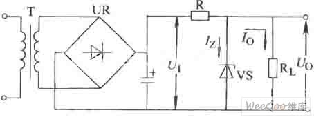
Simple Series Adjustable Regulator Circuit
Published:2011/7/18 5:26:00 Author:Felicity | Keyword: Simple Series Adjustable, Regulator Circuit
View full Circuit Diagram | Comments | Reading(626)
Voltage-stabilizing circuit having portable compact silicon regulator
Published:2011/7/20 0:42:00 Author:Fiona | Keyword: portable compact silicon regulator, Voltage-stabilizing

Voltage-stabilizing circuit having portable compact silicon regulator is shown as above:
(View)
View full Circuit Diagram | Comments | Reading(520)
15V,-6V double lines regulated power supply circuit
Published:2011/7/20 0:41:00 Author:Fiona | Keyword: double lines, regulated power supply

15V,-6V double lines regulated power supply circuit is shown as above:
(View)
View full Circuit Diagram | Comments | Reading(717)
compact 15V,1A parallel regulated power supply circuit
Published:2011/7/17 7:42:00 Author:Fiona | Keyword: parallel regulated power supply

compact 15V,1A parallel regulated power supply circuit is shown as above:
(View)
View full Circuit Diagram | Comments | Reading(664)
±18V bipolar regulated power supply circuit
Published:2011/7/18 0:04:00 Author:Fiona | Keyword: bipolar regulated power supply

±18V bipolar regulated power supply circuit is shown as above: (View)
View full Circuit Diagram | Comments | Reading(1232)
0~20v,1A regulated power supply circuit
Published:2011/7/17 7:36:00 Author:Fiona | Keyword: regulated power supply

0~20v,1A regulated power supply circuit is shown as above:
(View)
View full Circuit Diagram | Comments | Reading(1385)
LM317 Current-Expansion Circuit (2)
Published:2011/7/16 6:29:00 Author:Robert | Keyword: Current, Expansion

The picture shows the LM317 current-expansion circuit (2).
This circuit is also OK. But its output voltage may be unstable. Because the LM317's pin 1-2 is the reference voltage and the output voltage would minus the power transistor's B-E junction voltage. Not only this, the B-E junction voltage also would decrease while the transistor's temperature increasing. So the output voltage mey be unstable and it's not recommended to do this. (View)
View full Circuit Diagram | Comments | Reading(4909)
LM317 Current-Expansion Circuit (1)
Published:2011/7/16 7:42:00 Author:Robert | Keyword: Current, Expansion

The picture shows the LM317 current-expansion circuit (1).
The input voltage is VIN.
The Q1 needs a large-enough heatsink.
The Q2 needs a adequate heatsink.
The output voltage is 1.25V-15V/5A. (View)
View full Circuit Diagram | Comments | Reading(3102)
Numerical Control D. C. Regulated Power Supply Four
Published:2011/6/14 12:55:00 Author:Michel | Keyword: Numerical Control, D. C., Regulated Power Supply, Four

The numerical control D. C. regulated power supply circuit introduced in the example adopts LED to indicate output voltage's magnitude with features of visual display,convenient operation,high-precision voltage regulation.Its output voltage range is 0-9.9V and output current is 5A.
Circuit's Work principle
The numerical control D. C. regulated power supply circuit is composed of power regulation voltage circuit,operation and control circuit,display driver circuit,D/A converter circuit and regulated output circuit and it is showed as the picture 5-23.The power regulation voltage consists of mains switch,S,fuse,FU,mains transformer,T,rectifier bridge,UR1-UR3,capacitor,C1,C3-C13 and voltage regulation IC,IC8-IC10. (View)
View full Circuit Diagram | Comments | Reading(805)
Numerical Control D. C. Regulated Power Supply Fourteen
Published:2011/6/14 12:54:00 Author:Michel | Keyword: Numerical Control, D. C., Regulated Power Supply, Fourteen

The numerical control D. C. power-supply circuits-fixed introduced in the example uses single button control means and its magnitude of output voltage are divided into six grades,namely,1.5 V,3V,5V,6V,9V and 12V.Its output power is 20W.Its femature is that open it after cutting off utility power and the output voltage is the lowest voltage,1.5V
Work's Principle of the Circuit
The numerical control D. C. power-supply circuits-fixed is composed of input constant voltage circuit,impulsator,control output or indication circuit and it is showed as the picture5-33.The input constant voltage circuit consists of ,switch,S1,mains transformer,T,rectifier bridge,UR,filter capacitor,C1,C2,current-limiting resistor,RO and voltage regulator diode,VS. (View)
View full Circuit Diagram | Comments | Reading(834)
printed circuit board with enough creepage distance in the high voltage circuit
Published:2011/6/15 5:13:00 Author:chopper | Keyword: printed circuit board, creepage distance, high voltage circuit


In the power supply circuit,there should be enough interval among lines for security.The interval is usually called creepage distance. A side circuit often should be added 220V voltage or above,therefore we needa creepage distance that can stand the high voltage.The usual creepage distance is 5OOV/1mm.But the distance is not enough if it is used in the high humidity environment.In this case, non-corroding resin should be printed on the surface of printed plate and so does the dampproof coating.Additionally,high voltage circuit can increase creepage distance by slotting the lines,just as follows.
(View)
View full Circuit Diagram | Comments | Reading(1276)
IR4010 internal schematic box circuit
Published:2011/6/30 11:23:00 Author:John | Keyword: schematic box

The figure shows the IR4010 internal schematic box circuit, which indicates the internal circuit components of IR4010 device. It should be noted that it provides the VCC (voltage input response) with over or under voltage protection. When the VCC is equal to16 V, the control circuit starts to work with 6 V lag lock function. It refers that the circuit does not work with under-voltage protection when the VCC is less than (including) 10V. When the VCC is larger than 22V, the circuit does not work the either but with over-voltage protection.
Comparator COMP1 controls the on-and off of the MOSFET. When the VTH (1) is larger than (including).7 V, turn off the MOSFET. Comparator COMP2 controls the connection of the MOSFET. When VTH (2) is less than (including) 1.45 V, the MOSFET is connected.
(View)
View full Circuit Diagram | Comments | Reading(807)
Serial adjustable voltage regulator circuit
Published:2011/6/15 4:55:00 Author:John | Keyword: Serial adjustable voltage regulator

Serial adjustable voltage regulator circuit is shown below.
(View)
View full Circuit Diagram | Comments | Reading(872)
Numerical Control D. C. Regulated Power Supply Three
Published:2011/6/2 10:57:00 Author:Michel | Keyword: Numerical Control, D. C. , Regulated Power Supply, Three

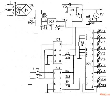
The numerical control D. C. power-supply circuits-fixedintroduced in the example uses dallastat and three-terminal tunable voltage regulatoion IC to regulate the voltage and adopts LED,voltmeter to indicate voltage.
Circuit's Work Principle
The numerical control D. C. regulated power supply circuit is composed of power converting circuit,+5V voltage regulation circuit,voltage regulation control output circuit and LED indication circuit and it is showed as the picture 5-22.The power converting circuit consists of mains transfomer,T,rectifier bridge,UR and filter capacitor,CO.The +5V voltage regulation circuit is composed of resistor,R1,capacitor,C1 and C2 and three-terminal voltage regulation IC,IC5.
(View)
View full Circuit Diagram | Comments | Reading(736)
Numerical Control D. C. Regulated Power Supply Two
Published:2011/6/2 10:54:00 Author:Michel | Keyword: Numerical Control D. C. Regulated Power Supply, Two

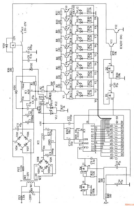
The numerical control D. C. regulated power supply circuit introduced in the example is controlled by tuch-button and digital integrated circuit.Its output voltage range is 1.5-37V divided into low voltage(1.5-15V) and high voltage(16.5-37V).
Circuit's Work PrincilpeThis circuit i scomposed of power supply input converting circuit,+5V voltage regulation circuit,functional mode indicating circuit and control circuit and it is showed as the picture 5-21.The power supply input converting circuit consists of fuse,FU1 and FU2,piezoresistor,RV,mains transformer,T and commutation diode,VD4-VD11.The +5V voltage regulation circuit is composed of filter capacitor,C4 and C5 and three-terminal voltage regulation IC,IC2.
(View)
View full Circuit Diagram | Comments | Reading(2654)
Numerical Control D. C. Regulated Power Supply Thirteen
Published:2011/6/2 11:11:00 Author:Michel | Keyword: Numerical Control, D. C., Regulated Power Supply, Thirteen

The numerical control D. C. power-supply circuits-fixed introduced in the example only uses one touch electrode and its magnitude of output voltage are divided into 8 grades,namely,3V,4.5V,5V,6V,7.5V,9V,12V and 15V.Its maximum current is 2A.
Work's Principle of the Circuit
The numerical control D. C. power-supply circuits-fixed consists of constant voltage control circuit and touch control circuit and it is showed as the picture 5-30.The constant voltage control circuit is composed of mains switch,S,fuse,FU1,FU2,mains transformer,T,commutation diode,VD1-VD4,capacitor,C1-C4,C6,resistor,RO,R1,voltage regulator diode,VS and three-terminal integrated regulator,IC1. (View)
View full Circuit Diagram | Comments | Reading(1000)
Numerical Control D. C. Regulated Power Supply Tweleve
Published:2011/6/2 11:11:00 Author:Michel | Keyword: Numerical Control, D. C., Regulated Power Supply, Tweleve

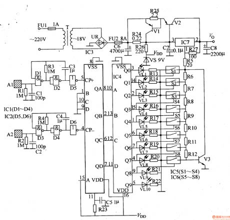
The numerical control D. C. power-supply circuits-fixed introduced in the example controls the magnitude of the voltage by touching the sheet metal by fingers.Its magnitudeof the output voltage are divided into 8 gardes ,namely,1.5V,3V,4.5V,6V,7.5V,9V and 12V which uses LED to indicate and it's convenient.
Work's Principle of the Circuit
The numerical control D. C. power-supply circuits-fixed is composed of trigger generator circuit and counter,encoder,,switch control circuit and constant voltage and it is showed as the picture 5-31.
The trigger generator circuit consists of touching sheet metal,A1,A2,NOT-gate IC1(D1-D4),NOT-gate IC,IC2(D5,D6),resistor,R1-R4,capacitor,C1-C4. (View)
View full Circuit Diagram | Comments | Reading(1108)
Numerical Control D. C. Regulated Power Supply Eleven
Published:2011/6/2 11:10:00 Author:Michel | Keyword: Numerical Control, D. C., Regulated Power Supply, Eleven

The numerical control D. C. power-supply circuits-fixed introduced in the example only uses one touch electrode and its magnitude of output voltage are divided into 8 grades,namely,3V,4.5V,5V,6V,7.5V,9V,12V and 15V.Its maximum current is 2A.
Work's Principle of the Circuit
The numerical control D. C. power-supply circuits-fixed consists of constant voltage control circuit and touch control circuit and it is showed as the picture 5-30.The constant voltage control circuit is composed of mains switch,S,fuse,FU1,FU2,mains transformer,T,commutation diode,VD1-VD4,capacitor,C1-C4,C6,resistor,RO,R1,voltage regulator diode,VS and three-terminal integrated regulator,IC1. (View)
View full Circuit Diagram | Comments | Reading(1045)
Numerical Control D. C. Regulated Power Supply Ten
Published:2011/6/2 11:09:00 Author:Michel | Keyword: Numerical Control, D. C., Regulated Power Supply, Ten

The output voltage of the numerical control D. C. power-supply circuits-fixed introduced in the example are divided into 8 grades,namely,3V,4.5V,5V,6V,7.5V,9V,l2V and l5V.Its maximum current is 2A.
Work's Principle of the Circuit
The numerical control D. C. power-supply circuits-fixed consists of constant voltage control circuit and touch control circuit and it is showed as the picture 5-29.
The constant voltage control circuit is composed of mains switch,S,fuse,FU,mains transformer,T,rectifier bridge,UR,filter capacitor,C1 and five-terminal adjustable integrated regulator,IC2.The touch control circuit is composed of touch electrode slice,A1-A8,resistor,R1-R6,transistor,V1-V8 and electronic switching IC,IC2. (View)
View full Circuit Diagram | Comments | Reading(720)
Numerical Control D. C. Regulated Power Supply Nine
Published:2011/6/2 11:08:00 Author:Michel | Keyword: Numerical Control, D. C., Regulated Power Suppl, Nine

The output voltage of the numerical control D. C. power-supply circuits-fixed introduced in the example is from +1.5V to 12V with 8 adjustable grades and its maximum current is 1.5A.
Work's Principle of the Circuitnumerical control D. C. power-supply circuits-fixed consists of +12V voltage constant voltage control circuit,voltage control or indication circuit and constant voltage output circuit and it is showed as the 5-28 picture.
The +12V voltage constant voltage control circuit consists of mains switch,SO,mains transformer,T,rectifier bridge,UR,resistor,RI,voltage regulator diode,VS,and filter capacitor,C1,C2,C7.The voltage control or indication circuit is composed of reset button,S1,control button,S2,resistor,R2-R6,regulation resistance,RP and capacitor,C5,C6,C8 (View)
View full Circuit Diagram | Comments | Reading(871)
| Pages:3/14 1234567891011121314 |
Circuit Categories
power supply circuit
Amplifier Circuit
Basic Circuit
LED and Light Circuit
Sensor Circuit
Signal Processing
Electrical Equipment Circuit
Control Circuit
Remote Control Circuit
A/D-D/A Converter Circuit
Audio Circuit
Measuring and Test Circuit
Communication Circuit
Computer-Related Circuit
555 Circuit
Automotive Circuit
Repairing Circuit
