
Measuring and Test Circuit
Index 17
Pressure gauge circuit with magnetic components
Published:2012/11/20 20:30:00 Author:Ecco | Keyword: Pressure gauge, magnetic components

The circuit uses magnetic components FP210P250, and they form a bridge circuit with two 1kΩ resistors and connected to the input terminal of the operational amplifier. Bridge voltage is stablized by regulator in order to make it independent from supply voltage fluctuations. It uses the distance between feedback resistors R1 and small iron piece magnetic components to realize stroke control the size of the output current.
(View)
View full Circuit Diagram | Comments | Reading(1321)
Three-phase motor speed measured with a multimeter
Published:2012/11/20 1:58:00 Author:Ecco | Keyword: Three-phase , motor speed , multimeter
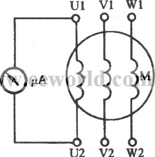
In the Figure, μA uses the multimeter 50μA block ( it is also available to use 1mA block ). It is connected with any winding of three-phase stator windings, then slowly turning the motor rotor can make rotor run in the uniform speed. There is always a certain amount of remanent magnetization of the used motor, when the rotor is rotated, the magnetic force will cut lines, then the electromotive force is induced in the stator windings, there is current flowing through the ammeter swing.
(View)
View full Circuit Diagram | Comments | Reading(1565)
Audio Level Meter circuits
Published:2012/11/19 21:48:00 Author:muriel | Keyword: Audio Level , Meter circuits

Audio levels can be monitored using a small panel meter with this circuit built from discrete components. (View)
View full Circuit Diagram | Comments | Reading(2092)
Audio VU Meter circuit
Published:2012/11/19 21:46:00 Author:muriel | Keyword: Audio, VU Meter circuit
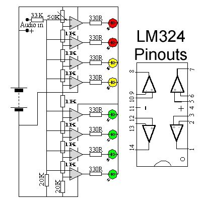
This circuit uses two quad op-amps to form an eight LED audio level meter. The op-amp used in this particular circuit is the LM324. It is a popular IC and should be available from many parts stores. (View)
View full Circuit Diagram | Comments | Reading(2484)
Audio Peak Level Meter
Published:2012/11/19 21:38:00 Author:muriel | Keyword: Audio, Peak Level , Meter
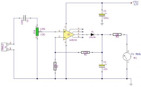
Using a single MOSFET Op-amp this circuit samples the audio input and displays peak readings. (View)
View full Circuit Diagram | Comments | Reading(1379)
Wideband RF Field Strength Meter
Published:2012/11/15 21:15:00 Author:muriel | Keyword: Wideband, RF , Field , Strength Meter
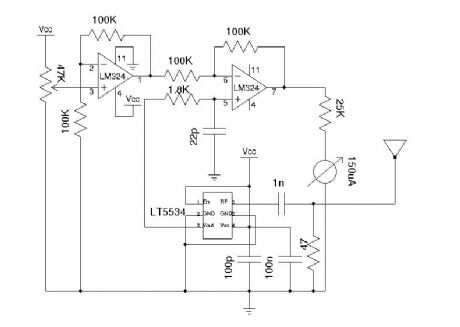
Field strength meter is extremely useful when working with RF devices. It can be used to quickly diagnose whether a transmitter circuit is working, and can be used to detect RF signals in the environment. The simplest field strength meter could be built with a tuned LC circuit and a germanium diode, just like the way of a building a crystal radio except replacing the ear piece with a high sensitivity current meter. While this approach fits the needs of most simple applications, it has a pretty narrow frequency range (~100 MHz) and requires tuning the LC circuit to the correct frequency before measurements can be made and the design can become complicated if wider frequency range tuning is desired. (View)
View full Circuit Diagram | Comments | Reading(1496)
Simple RF Power Meter
Published:2012/11/15 1:01:00 Author:muriel | Keyword: Simple , RF , Power Meter
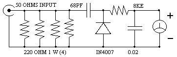
Here is a simple set up which will enable them to measure the out put power of their transmitter. All that they require is a good multimeter which has a sensitivity of 20k ohms/4 Watts which is adequate for low power transmitters. Many beginners trying out their skill with QRP TX, for the first time have to overcome many problems before they are able to come on the air. On usual complaint is that, every thing is working fine but the signal is not going out.
The 8k resistor should be kept close to the out put terminal of the transmitter. Switch on the transmitter in the CW mode and measure the DC voltage with the multimeter. If the voltage is V then the out put power is given by Power = V^2/50
(View)
View full Circuit Diagram | Comments | Reading(2423)
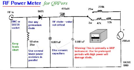
RF Power Meter
Published:2012/11/15 0:49:00 Author:muriel | Keyword: RF , Power Meter
View full Circuit Diagram | Comments | Reading(0)
RF Field Strength Meter with Attenuator up to 200 MHz
Published:2012/11/15 0:48:00 Author:muriel | Keyword: RF, Field Strength Meter , Attenuator, 200 MHz

RF Field Strength Meter with Attenuator up to 200 MHz The RF field meter unit is a great help to tune transmitters for best performance and output power. You can measure the radiated energy field and can easy tune the system for max output field strength maximum power. This field strength meter comes with selectable attenuator. You can use it for measuring the antenna gain and pattern, compare different magnetic field strengths. See the following RF field strength meter schematic. (View)
View full Circuit Diagram | Comments | Reading(2091)
RF Field Strength Meter
Published:2012/11/15 0:47:00 Author:muriel | Keyword: RF , Field Strength Meter
Most transmitter has several variable capacitors which are used to match impedance for transistors and antennas. I know people hate trimmers and so did I. The reason is that it is difficult to trim a system if you can't measure the performances. To trim a transmitter you need to measure the output power. Most transmitter are tuned with a dummy load of 50 ohm to substitute an antenna of 50 ohm. Not everyone has a power meter, and how can you know that the antenna you connect is purely 50 ohm. If not, the hole trimming is waste of time! What you would like to do is to measure the radiated power out from the antenna you actually are going to use. If you can measure the radiated energy field you can easy tune the system for max output field strength (max power). So, how can we measure the radiated energy field? The block diagram at right show you one easy way to measure the RF filed strength. To the left you find a dipole antenna. The antenna should be cut to match the receiving frequency ... (View)
View full Circuit Diagram | Comments | Reading(3569)
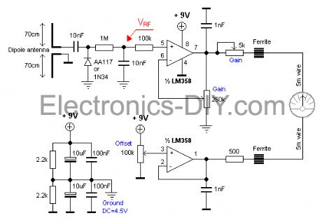
A Wide Dynamic Range Field Strength Meter
Published:2012/11/14 0:37:00 Author:muriel | Keyword: Wide Dynamic Range , Field Strength Meter

This unit is an updated version of the Wide Dynamic Range Field Strength Meter. While the basic function is the same, it has several critical differences: It uses a specialized integrated circuit, the Analog Devices AD8307. This chip is designed specifically as a logarithmic amplifier for use through 500 MHz. Using the AD8307, it has a wider dynamic range (85 dB versus 55 dB) and it has built-in temperature compensation. Because of the different nature of this type of detector - and the fact that it has temperature compensation - means that there is no need for a zeroing control. One disadvantage of this approach as compared to the diode approach is that the AD8307 has a lower frequency response than the diode. The frequency limit of the meter is dictated pretty much by the diodes themselves along with their physical layout and related components: There is no reason why the earlier version could not be constructed to work through 10 GHz or so - but the AD8307 is falling flat by the time you get to 1 GHz, making it unsuitable for detecting wireless LANs or PCS-type cell phones. (View)
View full Circuit Diagram | Comments | Reading(2594)
30W Digital RF Wattmeter
Published:2012/11/11 20:23:00 Author:muriel | Keyword: 30W , Digital , RF Wattmeter
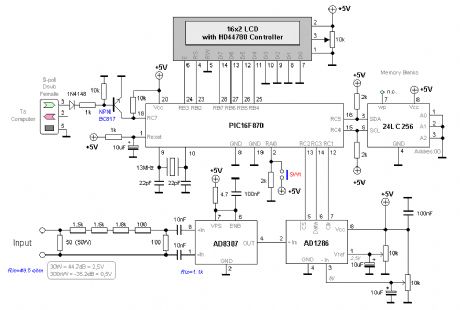
This project will explain how I build my new wattmeter. This watt meter will be able to measure power from 300nW to 30W @ (0-500MHz). This wattmeter is based up on a dummy load of 50 ohm which can handle 50W. The measurement will be displayed in Watt on a 2x16 Char display. (View)
View full Circuit Diagram | Comments | Reading(3986)
1GHZ Frequency Meter
Published:2012/11/11 20:00:00 Author:muriel | Keyword: 1GHZ , Frequency , Meter

This is 1GHz frequency counter with 100KHz resolution. Meter is built in around PIC16F84A microcontroller and SAB6456 / U813BS prescaller. (View)
View full Circuit Diagram | Comments | Reading(4236)
0-500MHz PIC16F876 RF Power Meter
Published:2012/11/9 20:48:00 Author:muriel | Keyword: 0-500MHz, PIC16F876 , RF, Power Meter
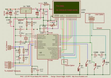
RF Measurement has been an expensive work so far the cost of measuring instruments are concerned. RF Meter is based on PIC16F876 microcontroller, AD8307 and 2x20 LCD display. Full documentation is included. (View)
View full Circuit Diagram | Comments | Reading(4362)
TX200 Power Meter
Published:2012/11/9 20:44:00 Author:muriel | Keyword: TX200, Power Meter
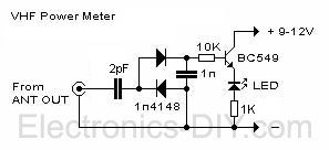
TX200 comes with built-in LED based power meter. This is a very helpful tool that will tell you if your transmitter's oscillator is working properly. If RF signal is transmitted the LED will illuminate. Besides that, it will also give you a quick visual way to check how much power is being transmitted. I highly recommend that you have the transmitter and power meter on the same PCB. If you like to experiment a lot, you will appreciate this inexpensive but externally helpful addition. (View)
View full Circuit Diagram | Comments | Reading(1715)
Recommended Drift Test Circuit
Published:2012/11/9 0:14:00 Author:muriel | Keyword: Recommended, Drift Test Circuit

View full Circuit Diagram | Comments | Reading(914)
SPI bus high-precision pressure test system circuit diagram
Published:2012/11/8 20:38:00 Author:Ecco | Keyword: SPI bus, high-precision , pressure test system
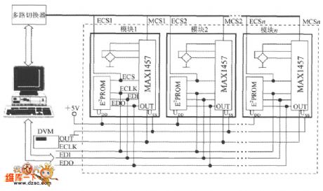
It uses a MAX1457 and a 27C64 to match with piezoresistive pressure sensor and constitute a pressure measurement module. N pieces of pressure measurement module with the computer and digital voltmeter form a PI bus high-precision pressure test system circuit. It consists of six transmission lines including two power supply lines (UDD, USS), an analog voltage output line ( out , pick digital voltmeter ) and three SPI interface lines (ECLK, EDI and EDO ).
(View)
View full Circuit Diagram | Comments | Reading(1395)
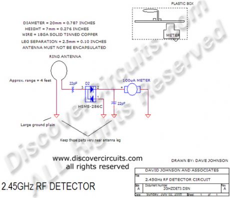
2.45GHz RF Signal Detector
Published:2012/11/8 0:59:00 Author:muriel | Keyword: 2.45GHz , RF Signal Detector
View full Circuit Diagram | Comments | Reading(1501)
Logic level test circuit
Published:2012/10/31 21:20:00 Author:Ecco | Keyword: Logic level test
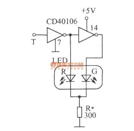
CD40106 is the six inverter with Schmitt trigger (only two of them ), T is the probe, when the T in contact with a point of 0 , after inverting driver, LED - R emits red light, LED-G is extinguished; when the detection point is 1 , the LED- R is turned off because of reverse bias, and after twice inverting, LED - G emits green light; when T probe detects CP pulse, two diodes are lit alternately. When clock frequency is higher than 24Hz, since the visual pictures effect, two diodes look flashing at the same time, rather than alternately flashing, so they emit orange- red light.
(View)
View full Circuit Diagram | Comments | Reading(1892)
Digital Radar Speedometer
Published:2012/10/29 0:55:00 Author:muriel | Keyword: Digital Radar Speedometer

This circuit is a Digital Radar Speedometer. It allows us to evaluate the speed of any object moving, especially cars and other vehicles. The speed is calculated in kilometers per hour (KPH). Its display has three digits. This radar works with the laser reflexion. It sends laser radiation to the object and this object reflects the laser radiation to the radar. To evaluate the speed of a vehicle, we must be in front of it. In other words, the vehicle must come in our direction. The front of the radar must point the front of the vehicle. The radar has the shape of a pistol. In this radar, it has a laser LED and a laser diode. Both have a lens.
The laser LED can send a spot of light to a distance of 90 m (295 ft). It's very important that the distance range of the laser LED is 90 m, if not, the speed will not be calculated properly. The laser diode, which receives the light signal by the laser LED, must be able to detect the light which is same color as that emitted by the laser LED. The laser diode and the laser LED must be placed one beside the other. They are protected by a tinted pane. They must be placed at the front of the radar and point the outside. The radar is powered by a 9V battery and it has a SPST switch to control its power state.
The display, or the speed indicator, is placed at the rear of the radar, just on the right of the overload LED indicator. All the logic components of the circuit must be of the 74AS series and TTL type. Because they have short time of response (less than 1.7 ns) and have high frequency supports (more than 200 MHz). The radar can evaluate the speed of an object moving between 0 to 999 km/h. After this speed, the overload LED indicator will turn on and the 999 will still displayed. The radar displays the speed during 3 seconds, after this time, it displays zero (0). (View)
View full Circuit Diagram | Comments | Reading(2056)
| Pages:17/101 1234567891011121314151617181920Under 20 |
Circuit Categories
power supply circuit
Amplifier Circuit
Basic Circuit
LED and Light Circuit
Sensor Circuit
Signal Processing
Electrical Equipment Circuit
Control Circuit
Remote Control Circuit
A/D-D/A Converter Circuit
Audio Circuit
Measuring and Test Circuit
Communication Circuit
Computer-Related Circuit
555 Circuit
Automotive Circuit
Repairing Circuit