Measuring and Test Circuit
Index 16
Multi Wire Cable Tester
Published:2012/12/3 20:39:00 Author:muriel | Keyword: Multi , Wire Cable Tester
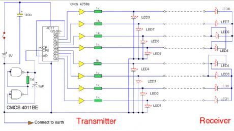
A multi wire cable tester with a separate LED for each wire. Will show open circuits, short circuits, reversals, earth faults, continuity and all with four IC's. Designed initially for my intercom, but can be used with alarm wiring, CAT 5 cables and more. (View)
View full Circuit Diagram | Comments | Reading(1947)
Milligaus Meter
Published:2012/12/3 20:39:00 Author:muriel | Keyword: Milligaus Meter

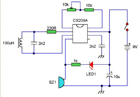
The circuit of Fig.1 provides an easy yet reliable way to detect the intensity of a.c. (or e.l.f.) fields around the home or workplace. It is doubly effective because it does not merely detect the electromagnetic radiation emitted by electrical appliances, but the electromagnetic energy actually absorbed by the body. (View)
View full Circuit Diagram | Comments | Reading(1119)
EMF Probe with Meter
Published:2012/12/3 20:36:00 Author:muriel | Keyword: EMF Probe , Meter

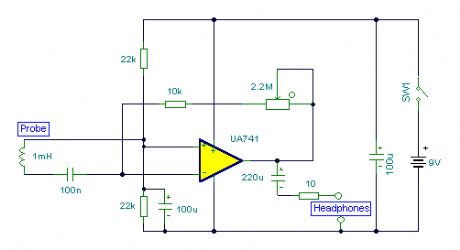
An electromagnetic field probe designed to detect changing electric and magnetic fields. The probe has a meter output and headphone socket as well. (View)
View full Circuit Diagram | Comments | Reading(1777)
Infra Red Remote Control Tester
Published:2012/12/3 20:36:00 Author:muriel | Keyword: Infra Red, Remote Control, Tester

A simple IR receiver to facilitate in testing of Infra Red Remote Control handsets. (View)
View full Circuit Diagram | Comments | Reading(1147)
Zener Diode Tester
Published:2012/12/3 20:35:00 Author:muriel | Keyword: Zener Diode, Tester
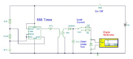
I have teamed up with Magazine Mikro Elektronica for this project. Please visit their site. I am very grateful to Aleksandar Dakic for the kind translation into Serbian and Romanian languages. (View)
View full Circuit Diagram | Comments | Reading(1438)
A single chip metal detecor
Published:2012/12/3 0:47:00 Author:muriel | Keyword: single chip, metal detecor
View full Circuit Diagram | Comments | Reading(1030)
Electromagnetic Field Detector
Published:2012/12/3 0:28:00 Author:muriel | Keyword: Electromagnetic Field Detector
View full Circuit Diagram | Comments | Reading(2045)
Lightning Detectors
Published:2012/12/3 0:26:00 Author:muriel | Keyword: Lightning Detectors
View full Circuit Diagram | Comments | Reading(1421)
Static Detector Negative Ion Detector
Published:2012/12/3 0:23:00 Author:muriel | Keyword: Static Detector, Negative Ion Detector
View full Circuit Diagram | Comments | Reading(1377)
Level test circuit using voltage comparator LM324
Published:2012/12/2 21:54:00 Author:Ecco | Keyword: Level test , voltage comparator
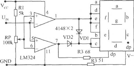
It is facilitate to test the threshold level adjustment, and the DTL, TTL, CMOS, and other logic level. It is known from voltage compator: when the voltage on non -inverting input terminal (positive side) is higher than inverting input terminal (negative side), the comparator output is high; in contrary, the output is low. RP is the comparison voltage adjustment potentiometer, when UIN is higher than the set voltage, the output of pin 7 is high, it displays 1 and the decimal point dp emit light.
(View)
View full Circuit Diagram | Comments | Reading(7222)
Temperature measuring circuit with 5 channel low power programmable sensor signal processor AD7714 and Platinum thermal resistor Pt100 (PRTD)
Published:2012/11/29 0:55:00 Author:Ecco | Keyword: Temperature measuring, 5 channel , low power , programmable sensor , signal processor , Platinum , thermal resistor

Pt100 uses 4-wire connection to eliminate pressure drop on lead resistors RL2 and RL3. External 400 μA current source provides excitation current for PT100, and then it will generate AD7714 voltage reference after passing 6.25kΩ resistor. Because the input voltage and reference voltage changes and the excitation current changes are proportional, the changes do not affect the measurement accuracy of the excitation current. But in order to avoid voltage reference from the effects of temperature changes, 6.25kΩ resistor should use metal film resistors with low temperature coefficient.
(View)
View full Circuit Diagram | Comments | Reading(3421)
High-accuracy pressure measurement system circuit diagram composed of intelligent dual-channel sensor signal processor MAX1463
Published:2012/11/29 0:50:00 Author:Ecco | Keyword: High-accuracy , pressure measurement system , intelligent , dual-channel sensor, signal processor
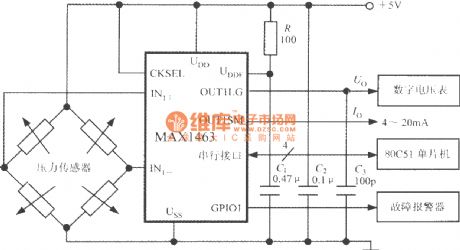
Bridge pressure sensor's output voltage is connected to the MAX1463 IN1+ IN1-side. Under CPU control, pressure signal is converted by nonlinear calibration, temperature compensation and ADC conversion, then it is sent to 80C51 MCU after being output from the serial interface; DAC also can convert it to the analog output voltage Uo, then it is sent to a digital voltmeter to show the measured pressure value. GPI01 universal digital I/O interface pin is connected to failure alarm, and the leader of sensor is open or CPU occurs overflowing, it can drive the buzzer alarm to emit sounds.
(View)
View full Circuit Diagram | Comments | Reading(2208)
Pressure detection system with MAX1460 intelligent sensor signal processor and Silicon pressure sensor
Published:2012/11/29 0:41:00 Author:Ecco | Keyword: Pressure detection system , intelligent sensor , signal processor, Silicon pressure sensor


The system uses +5V power supply, and crystal oscillator frequency is 2MHz. R1 and R2 form a power divider, analog end (AGND) is connected to the mid-point of power supply. C is the power supply decoupling capacitor. Host can use PC, and MAX1460 is firstly tested by the host, then it receives the 12-bit parallel data output by MAX1460, and the test system is removed, MAX1460 and the testing sensor form a high precision intelligent pressure detection system, the conversion rate is 15 times/second, measuring error is less than ± 0. 1%.
(View)
View full Circuit Diagram | Comments | Reading(1198)
Light transformer checking current relay circuit
Published:2012/11/29 0:24:00 Author:Ecco | Keyword: Light transformer , checking , current relay

Lamp transformer usually uses 220/12/24/36 V power supply, and its capacity is 0.5kVA, it is mainly used for temporary lighting (low-voltage lamps). The current relay checking circuit is shown in the figure. According to relevant regulations, quick-break protection in power systems and overcurrent protection in the current relay should be checked on a regular basis once each year. According to the connection shown in above circuit, closing the knife switch QS, slowly adjusting the regulator TA, then the ammeter readings will be gradually increased to the AP KA dial number of current relay.
(View)
View full Circuit Diagram | Comments | Reading(1068)
Digital high accuracy pressure tester circuit (high-precision integrated pressure signal conditioner MAX1457)
Published:2012/11/23 2:52:00 Author:Ecco | Keyword: Digital, high accuracy , pressure tester , high-precision, integrated, pressure signal conditioner
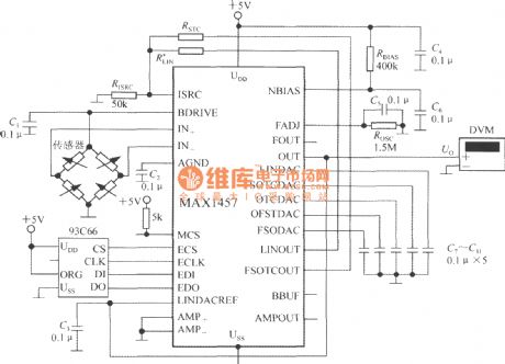
MAX1457 selects 93C66 4096b external read-only memory E2PROM. MCS-end is pulled into a high level after geting power, and it selects the main chip. +5V power supplyprovides partial pressurefor the bias circuit by the resistor RBIAS (400k). C2, C4 and C6 are the decoupling capacitors. C1, C3, C5, C7~C11are bypass capacitors. When you take RISRC=50k Ω, excitation current is 0. 5mA.
(View)
View full Circuit Diagram | Comments | Reading(1447)
Light Detector Circuit
Published:2012/11/29 0:26:00 Author:muriel | Keyword: Light Detector Circuit
View full Circuit Diagram | Comments | Reading(965)
Bug Detector
Published:2012/11/21 21:30:00 Author:muriel | Keyword: Bug Detector
View full Circuit Diagram | Comments | Reading(0)
Simple Field Strength Meter
Published:2012/11/21 21:23:00 Author:muriel | Keyword: Simple , Field Strength Meter
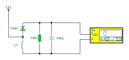
This Field Strength Meter is simple and also quite sensitive. It uses an ordinary digital voltmeter to measure RF signal strength up to a few hundred MHz. (View)
View full Circuit Diagram | Comments | Reading(0)
Field Strength Meter
Published:2012/11/21 21:22:00 Author:muriel | Keyword: Field Strength Meter

This is a wide band signal strength meter circuit which responds to small changes in RF energy, designed to be used for the VHF spectrum and will respond to AM or FM modulation or just a plain carrier wave. (View)
View full Circuit Diagram | Comments | Reading(0)
IR Remote Control Modulation Detector
Published:2012/11/21 2:05:00 Author:muriel | Keyword: IR, Remote Control , Modulation Detector
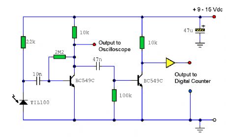
A circuit to extract and measure the modulated carrier of an Infra Red remote control. Note that the circuit does not physically separate control pulses from modulation, but amplifies the completereceived signal allowing the waveform to be displayed ideally on an oscilloscope or a frequency counter. Modulation frequencies between 1kHz and several MHz may be measured. (View)
View full Circuit Diagram | Comments | Reading(1393)
| Pages:16/101 1234567891011121314151617181920Under 20 |
Circuit Categories
power supply circuit
Amplifier Circuit
Basic Circuit
LED and Light Circuit
Sensor Circuit
Signal Processing
Electrical Equipment Circuit
Control Circuit
Remote Control Circuit
A/D-D/A Converter Circuit
Audio Circuit
Measuring and Test Circuit
Communication Circuit
Computer-Related Circuit
555 Circuit
Automotive Circuit
Repairing Circuit
