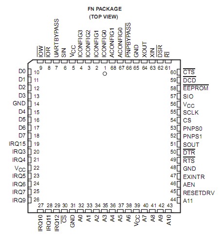
PinoutSpecificationsSupply voltage range, VCC (see Note 1). . . . . . . . . . . . . . . . . . 0.5 V to 7 VInput voltage range at any input, VI. . . . . . . . . . . . . . . . . .. . . 0.5 V to 7 V Output voltage range, VO. . . . . . . . . . . . . . . . . . . . . . . . . . . . . 0.5 V to 7 V Operati...
TL16PNP550A: PinoutSpecificationsSupply voltage range, VCC (see Note 1). . . . . . . . . . . . . . . . . . 0.5 V to 7 VInput voltage range at any input, VI. . . . . . . . . . . . . . . . . .. . . 0.5 V to 7 V Ou...
SeekIC Buyer Protection PLUS - newly updated for 2013!
268 Transactions
All payment methods are secure and covered by SeekIC Buyer Protection PLUS.
The TL16PNP550A is a functional upgrade of the TL16C550C asynchronous communications element (ACE), which in turn is a functional upgrade of the TL16C450. Functionally equivalent to the TL16C450 on power up (character or TL16C450 mode), the TL16PNP550A, like the TL16C550C, can be placed in an alternate mode (FIFO mode). This relieves the CPU of excessive software overhead by buffering received and transmitted characters. The receiver and transmitter FIFOs store up to 16 bytes including three additional bits of error status per byte for the receiver FIFO. In the FIFO mode, there is a selectable autoflow control feature that can
significantly reduce software overload and increase system efficiency by automatically controlling serial data flow using RTS output and CTS input signals.
The TL16PNP550A responds to the plug-and-play (PnP) autoconfiguration process. The autoconfiguration process puts all PnP cards in a configuration mode, isolates one PnP card at a time, assigns a card select number (CSN), and reads the card resource data structure from the EEPROM. After the resource requirements and capabilities are determined for all cards, the autoconfiguration process uses the CSN to configure the card by writing to the configuration registers. The TL16PNP550A only implements configuration registers for I/O applications with one logical device and no direct memory access (DMA) support. Finally, the process activates the TL16PNP550A card and removes it from configuration mode. After the configuration process, the ACE starts responding to industry standard architecture (ISA) bus cycles. This device can also be configured to bypass the PnP autoconfiguration sequence. In this mode the TL16PNP500A can be configured to select the COM port address and IRQ level. In the UART bypass mode, the UART is disabled and this device is configured to be a stand-alone PnP controller that supports one logical device and no DMA support.
The TL16PNP550A performs serial-to-parallel conversion on data received from a peripheral device or modem and parallel-to-serial conversion on data received from its CPU. The CPU can read and report on the status of the ACE operation. Reported status information includes the type of transfer operation in progress, the status of the operation, and any error conditions encountered.
The TL16PNP550A includes a clock prescalar that divides the 22-MHz input clock by 12, 6, 3, or 1. The prescalar output clock is fed to the programmable baud rate generator, which is capable of dividing this clock by divisors from 1 to (216 1).