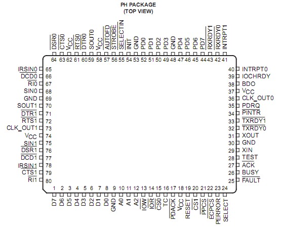
Pinout Specifications
Supply voltage range, VCC . . . . . . . . . . . . . . . . . . . . . . . . . . . . . . . . . . . . . . . . . . . . . . . . . . . . . . 0.5 V to 6 V
Input voltage range, VI . . . . . . . . . . . . . . . . . . . . . . . . . . . . . . . . . . . . . . . . . . . . . .. . . . 0.5 V to VCC + 0.5 V
Output voltage range, VO . . . . . . . . . . . . . . . . . . . . . . . . . . . . . . . . . . . . . . . . . . . . . . . . 0.5 V to VCC + 0.5 V
Input clamp current, IIK (VI < 0 or VI > VCC) (See Note 2) . . . . . . . . . . . . . . . . . . . . . . . .. . . . . . . . . . .±20 mA
Output clamp current, IOK (VO < 0 or VO > VCC) (See Note 3) . . . . . . . . . . . . . . . . . . . . . . . . . . . . . . . .±20 mA
Output clamp current, level shift, IOK (VO < 0 or VO > VCC) (See Note 3) . . . . . . . . . . . . . . . . . . . . . . . ±20 mA
Virtual junction, TJ . . . . . . . . . . . . . . . . . . . . . . . . . . . . . . . . . . . . . . . . . . . . . . . . . . . . . . . . . . . . . . . . . . 150°C
Storage temperature range, Tstg . . . . . . . . . . . . . . . . . . . . . . . . . . . . . . . . . . . . . . . . . . . . . . . 65°C to 150°C
† Stresses beyond those listed under "absolute maximum ratings" may cause permanent damage to the device. These are stress ratings only, and functional operation of the device at these or any other conditions beyond those indicated under "recommended operating conditions" is not implied. Exposure to absolute-maximum-rated conditions for extended periods may affect device reliability.
NOTES: 2. This applies to external input and bidirectional buffers. VI < VCC does not apply to fail-safe terminals.
3. This applies to external output and bidirectional buffers. VO < VCC does not apply to fail-safe terminals.
DescriptionThe TL16PIR552 has a dual-channel universal asynchronous receiver/transmitter (UART). The UART is similar to the TL16C550C. The device serves two serial input/output ports simultaneously in microcomputer or microprocessor-based systems. Each channel performs serial-to-parallel conversion on data characters received from peripheral devices or modems and parallel-to-serial conversion on data characters transmitted by the CPU. The complete status of each channel of the dual UART can be read by the CPU at any time during functional operation. The information obtained includes the type and condition of the transfer operation being performed and the error condition.
The receiver and transmitter FIFOs in the UARTs store up to 16 bytes including three additional bits of error status per byte for the receiver FIFO. In the FIFO mode, there is a selectable autoflow control feature that can significantly reduce software overload and increase system efficiency by automatically controlling serial data flow through RTS output and CTS input signals.
The TL16PIR552 UART includes a programmable baud-rate generator capable of dividing a reference clock by divisors from 1 to 65535 and producing a 16× reference clock for the internal transmitter logic. Provisions are also included to use this 16× clock for the receiver logic. The UART accommodates a 1-Mbaud serial rate (16-MHz input clock) so that a bit time is 1 µs and a typical character time is 10 µs (start bit, eight data bits, stop bit).
Each serial channel has a prescaler with programmable divisor values from 0 to 33. The serial ports also have a dedicated infrared serial data input (IRSIN0/1) and the serial data outputs multiplex between a RS-232-type serial output or an infrared serial data output. This is selected through an internal register bit and uses the same SOUT0/1 output terminals. The same UART circuit is used for the data path for the IrDA or the RS-232 operations. Channel 0 is powered up at IR0 and channel 1 is powered up during the RS-232 mode.
In addition to dual communication capabilities, the TL16PIR552 provides the user with an IEEE 1284 host side compatible, bidirectional, parallel data port. The parallel port operates in a compatible, FIFO, extended capability port (ECP) with RLE data decompression mode, and in a enhanced parallel port (EPP) mode. The default mode of operation is compatible with the Centronics printer port. The parallel port and the two serial ports provide IBM PC/AT™-compatible computers with a single device to serve a 3-port system.

 TL16PIR552 Data Sheet


