TL16PC564B

PinoutSpecificationsSupply voltage range, VCC . . . . . . . . . . . . . . . . . . . . . . . . . . . . . . . . . . . . . . . . . . . . . . . . . . . . . . .0.5 V to 6 VInput voltage range, VI (standard) . . . . . . . . . . . . . . . . . . . . . . . . . . . . . . . . . . . . . . . . . 0.5 V to VCC +...

product image

TL16PC564B Picture
SeekIC No. : 004520090 Detail

TL16PC564B: PinoutSpecificationsSupply voltage range, VCC . . . . . . . . . . . . . . . . . . . . . . . . . . . . . . . . . . . . . . . . . . . . . . . . . . . . . . .0.5 V to 6 VInput voltage range, VI (standa...

floor Price/Ceiling Price

Part Number:
TL16PC564B
Supply Ability:
5000

Price Break

  • Qty
  • 1~5000
  • Unit Price
  • Negotiable
  • Processing time
  • 15 Days
Total Cost: $ 0.00

SeekIC Buyer Protection PLUS - newly updated for 2013!

  • Escrow Protection.
  • Guaranteed refunds.
  • Secure payments.
  • Learn more >>

Month Sales

268 Transactions

Rating

evaluate  (4.8 stars)

Upload time: 2025/1/11

Payment Methods

All payment methods are secure and covered by SeekIC Buyer Protection PLUS.

Notice: When you place an order, your payment is made to SeekIC and not to your seller. SeekIC only pays the seller after confirming you have received your order. We will also never share your payment details with your seller.
Product Details

Description


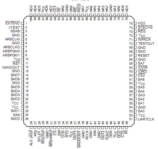
Pinout

  Connection Diagram


Specifications

Supply voltage range, VCC   . . . . . . . . . . . . . . . . . . . . . . . . . . . . . . . . . . . . . . . . . . . . . . . . . . . . . . .0.5 V to 6 V
Input voltage range, VI (standard)   . . . . . . . . . . . . . . . . . . . . . . . . . . . . . . . . . . . .  . . . . . 0.5 V to VCC + 0.5 V
Input voltage range, VI (fail safe)   . . . . . . . . . . . . . . . . . . . . . . . . . . . . . . . . . . . . . . . . . . . . . . . .0.5 V to 6.5 V
Output voltage range, VO (standard)   . . . . . . . . . . . . . . . . . . . . . . . . . . . . . . . . . . .. . . . . 0.5 V to VCC + 0.5 V
Output voltage range, VO (fail safe)   . . . . . . . . . . . . . . . . . . . . . . . . . . . . . . . . . . . . . . . . . . . . . .0.5 V to 6.5 V
Input clamp current, IIK (VI < 0 or VI > VCC) (see Note 1)  . . . . . . . . . . . . . . . . . . . . . . .. . . . . . . . . . . . ±20 mA
Output clamp current, IOK (VO < 0 or VO > VCC) (see Note 2)  . . . . . . . . . . . . . . . . . . . . . . . . . . . . . . . . ±20 mA
Operating free-air operating temperature range, TA  . . . . . . . . . . . . . . . . . . . . . . . . . . . . . . . . . . . .0°C to 70°C
Storage temperature range, Tstg  . . . . . . . . . . . . . . . . . . . . . . . . . . . . . . . . . . . . . . . . . . . . . . . 65°C to 150°C
† Stresses beyond those listed under "absolute maximum ratings" may cause permanent damage to the device. These are stress ratings only, and functional operation of the device at these or any other conditions beyond those indicated under "recommended operating conditions" is not implied. Exposure to absolute-maximum-rated conditions for extended periods may affect device reliability.
NOTES: 1. Applies for external input and bidirectional buffers. VI > VCC does not apply to fail-safe pins.
             2. Applies for external output and bidirectional buffers. VO > VCC does not apply to fail-safe pins.


Description

The TL16PC564B/BLV† is designed to provide all the functions necessary for a Personal Computer Memory Card International Association (PCMCIA) universal asynchronous receiver transmitter (UART) subsystem interface. This interface provides a serial-to-parallel conversion for data to and from a modem coder-decoder/digital signal processor (CODEC/DSP) function to a PCMCIA parallel data-port format. A computer central processing unit (CPU), through a PCMCIA host controller, can read the status of the asynchronous communications element (ACE) interface at any point in the operation. Reported status information includes the type of transfer operation in process, the status of the operation, and any error conditions encountered.

Attribute memory consists of a 256-byte card information structure (CIS) and eight 8-byte card configuration registers (CCR). The CIS, implemented with a dual-port random-access memory (DPRAM), is available to both the host CPU and subsystem (modem), as are the CCRs. This DPRAM is used in place of the electrically erasable programmable read-only memory (EEPROM) normally used for the CIS. At power up, attribute memory is initialized by the subsystem.

The TL16PC564B/BLV uses a TL16C550 ACE-type core with an expanded 64 × 11 receiver first-in-first-out (FIFO) memory and a 64 × 8 transmitter FIFO memory. The receiver trigger logic flags have been adjusted in order to take full advantage of the increased capacity when in the extended mode. In addition, eight of the UART registers have been mapped into the subsystem (modem) memory space as read-only registers. This allows the subsystem to read UART status information.

A subsystem-selectable serial-bypass mode has been implemented to allow the subsystem to bypass the serial portion of the UART and write directly to the receiver FIFO and read directly from the transmitter FIFO. Interrupt operation is not affected in this mode.


Customers Who Bought This Item Also Bought

Margin,quality,low-cost products with low minimum orders. Secure your online payments with SeekIC Buyer Protection.
Batteries, Chargers, Holders
Line Protection, Backups
Soldering, Desoldering, Rework Products
Industrial Controls, Meters
Resistors
View more