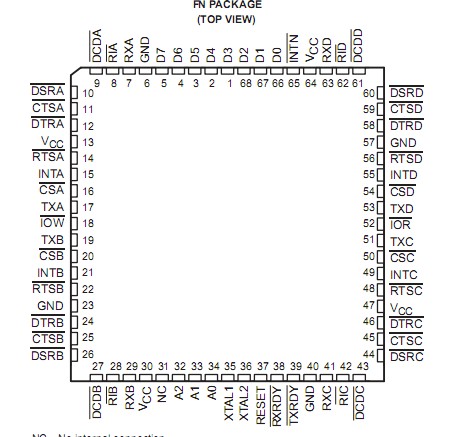
PinoutSpecificationsSupply voltage range, VCC (see Note 1) . . . . . . . . . . . . . . . . . . . . .0.5 V to 7 VInput voltage range at any input, VI . . . . . . . . . . . . . . . . . . . . . . . .0.5 V to 7 V Output voltage range, VO. . . . . . . . . . . . . . . . . . . . . . . . . . 0.5 V to VCC ...
TL16C554: PinoutSpecificationsSupply voltage range, VCC (see Note 1) . . . . . . . . . . . . . . . . . . . . .0.5 V to 7 VInput voltage range at any input, VI . . . . . . . . . . . . . . . . . . . . . . . .0....
SeekIC Buyer Protection PLUS - newly updated for 2013!
268 Transactions
All payment methods are secure and covered by SeekIC Buyer Protection PLUS.
The TL16C554 and the TL16C554I are enhanced quadruple versions of the TL16C550B asynchronous communications element (ACE). Each channel performs serial-to-parallel conversion on data characters received from peripheral devices or modems and parallel-to-serial conversion on data characters transmitted by the CPU. The complete status of each channel of the quadruple ACE can be read at any time during functional operation by the CPU. The information obtained includes the type and condition of the operation performed and any error conditions encountered.
The TL16C554 and the TL16C554I quadruple ACE can be placed in an alternate FIFO mode, which activates the internal FIFOs to allow 16 bytes (plus three bits of error data per byte in the receiver FIFO) to be stored in both receive and transmit modes. To minimize system overhead and maximize system efficiency, all logic is on the chip. Two terminal functions allow signaling of direct memory access (DMA) transfers. Each ACE includes a programmable baud rate generator that can divide the timing reference clock input by a divisor between 1 and (2161).
The TL16C554 and the TL16C554I are available in a 68-pin plastic-leaded chip-carrier (PLCC) FN package and in an 80-pin (TQFP) PN package.