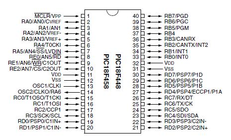
Features: • High current sink/source 25 mA/25 mA• Three external interrupt pins• Timer0 module: 8-bit/16-bit timer/counter with 8-bit programmable prescaler• Timer1 module: 16-bit timer/counter• Timer2 module: 8-bit timer/counter with 8-bit period register (time base ...
PIC18F448: Features: • High current sink/source 25 mA/25 mA• Three external interrupt pins• Timer0 module: 8-bit/16-bit timer/counter with 8-bit programmable prescaler• Timer1 module: 1...
SeekIC Buyer Protection PLUS - newly updated for 2013!
268 Transactions
All payment methods are secure and covered by SeekIC Buyer Protection PLUS.
SpecificationsDescriptionThe PIC1018SCL is one member of the PIC1018 family which is designed as o...
• High current sink/source 25 mA/25 mA
• Three external interrupt pins
• Timer0 module: 8-bit/16-bit timer/counter with 8-bit programmable prescaler
• Timer1 module: 16-bit timer/counter
• Timer2 module: 8-bit timer/counter with 8-bit period register (time base for PWM)
• Timer3 module: 16-bit timer/counter
• Secondary oscillator clock option Timer1/Timer3
• Capture/Compare/PWM (CCP) modules;CCP pins can be configured as:
- Capture input: 16-bit, max resolution 6.25 ns
- Compare: 16-bit, max resolution 100 ns (TCY)
- PWM output: PWM resolution is 1 to 10-bit Max. PWM freq. @:8-bit resolution = 156 kHz 10-bit resolution = 39 kHz
• Enhanced CCP module which has all the features of the standard CCP module, but also has the following features for advanced motor control:
- 1, 2 or 4 PWM outputs
- Selectable PWM polarity
- Programmable PWM dead time
• Master Synchronous Serial Port (MSSP) with two modes of operation:
- 3-wire SPI™ (Supports all 4 SPI modes)
- I2C™ Master and Slave mode
• Addressable USART module:
- Supports interrupt-on-address bit
Parameter Name | Value |
Program Memory Type | Flash |
Program Memory (KB) | 16 |
CPU Speed (MIPS) | 10 |
RAM Bytes | 768 |
Data EEPROM (bytes) | 256 |
Digital Communication Peripherals | 1-A/E/USART, 1-MSSP(SPI/I2C) |
Capture/Compare/PWM Peripherals | 1 CCP, 1 ECCP |
Timers | 1 x 8-bit, 3 x 16-bit |
ADC | 8 ch, 10-bit |
Comparators | 2 |
CAN | 1 ECAN |
Temperature Range (C) | -40 to 125 |
Operating Voltage Range (V) | 2 to 5.5 |
Pin Count | 40 |
Ambient temperature under bias............................................-40°C to +125°C
Storage temperature ............................................................ -65°C to +150°C
Voltage on any pin with respect to VSS (except VDD, MCLR and RA4) ....... -0.3V to (VDD + 0.3V)
Voltage on VDD with respect to VSS ........................................... -0.3V to +7.5V
Voltage on MCLR with respect to VSS (Note 2) ........................... 0V to +13.25V
Voltage on RA4 with respect to VSS................................................ 0V to +8.5V
Total power dissipation (Note 1) ...............................................................1.0W
Maximum current out of VSS pin .............................................................300 mA
Maximum current into VDD pin ................................................................250 mA
Input clamp current, IIK (VI < 0 or VI > VDD) ........................................±20 mA
Output clamp current, IOK (VO < 0 or VO > VDD) ..................................±20 mA
Maximum output current sunk by any I/O pin............................................25 mA
Maximum output current sourced by any I/O pin ......................................25 mA
Maximum current sunk by all ports (combined) .......................................200 mA
Maximum current sourced by all ports (combined) ...................................200 mA
Note 1: Power dissipation is calculated as follows:
Pdis = VDD x {IDD IOH} + {(VDD VOH) x IOH} + (VOL x IOL)
2: Voltage spikes below VSS at the MCLR/VPP pin, inducing currents greater than 80 mA, may cause latch-up.Thus, a series resistor of 50-100 should be used when applying a "low" level to the MCLR/VPP pin rather than pulling this pin directly to VSS.