Features: • Power Managed modes:- Run: CPU on, peripherals on- Idle: CPU off, peripherals on- Sleep: CPU off, peripherals off
• Power Consumption modes:- PRI_RUN: 150 µA, 1 MHz, 2V- PRI_IDLE: 37 µA, 1 MHz, 2V- SEC_RUN: 14 µA, 32 kHz, 2V- SEC_IDLE: 5.8 µA, 32 kHz, 2V- RC_RUN: 110 µA, 1 MHz, 2V- RC_IDLE: 52 µA, 1 MHz, 2V- Sleep: 0.1 µA, 1 MHz, 2V
• Timer1 Oscillator: 1.1 µA, 32 kHz, 2V
• Watchdog Timer: 2.1 µA
• Two-Speed Oscillator Start-up
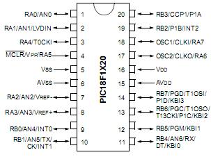
Pinout
Specifications
| Program Memory Type |
Flash |
| Program Memory (KB) |
8 |
| CPU Speed (MIPS) |
10 |
| RAM Bytes |
256 |
| Data EEPROM (bytes) |
256 |
| Digital Communication Peripherals |
1-A/E/USART, |
| Capture/Compare/PWM Peripherals |
1 ECCP |
| Timers |
1 x 8-bit, 3 x 16-bit |
| ADC |
7 ch, 10-bit |
| Temperature Range (C) |
-40 to 125 |
| Operating Voltage Range (V) |
2 to 5.5 |
| Pin Count |
18 |
Ambient temperature under bias........................................................... .-40°C to +125°C
Storage temperature ............................................................................ -65°C to +150°C
Voltage on any pin with respect to VSS (except VDD, MCLR and RA)...0.3V to (VDD + 0.3V)
Voltage on VDD with respect to VSS .......................................................... -0.3V to +5.5V
Voltage on MCLR with respect to VSS (Note 2) ........................................... 0V to +13.25V
Voltage on RA4 with respect to Vss................................................................. 0V to +8.5V
Total power dissipation (Note 1) ...............................................................................1.0W
Maximum current out of VSS pin ...........................................................................300 mA
Maximum current into VDD pin ..............................................................................250 mA
Input clamp current, IIK (VI < 0 or VI > VDD)...................................................... ±20 mA
Output clamp current, IOK (VO < 0 or VO > VDD) ............................................... ±20 mA
Maximum output current sunk by any I/O pin..........................................................25 mA
Maximum output current sourced by any I/O pin ....................................................25 mA
Maximum current sunk by all ports ........................................................................200mA
Maximum current sourced by all ports ...................................................................200 mADescriptionThis microcontroller has nanoWatt Technology, which features six enhanced power-managed "software controlled" modes, power consumption as low as 0.1 microamps in standby mode and a wide operating voltage range from 2- to 5.5-volts which makes this device PIC18F1320 ideal for battery managed applications. This device also encompasses a new low-current watchdog timer, a 2-speed start-up from a reset or sleep mode and a new fail-safe clock monitor that is used to detect an external clock failure.This powerful 10 MIPS (100 nanosecond instruction execution) yet easy-to-program (only 77 single word instructions) CMOS FLASH-based 10-bit microcontroller packs Microchip's powerful PIC18F1320 architecture into an 18-pin package and is upwards compatible with the PIC16C5X, PIC12CXXX, PIC16CXX and PIC17CXX devices and thus providing a seamless migration path of software code to higher levels of hardware integration. The PIC18F1220 features a 'C" compiler friendly development environment, 128 bytes of EEPROM, Self-programming, an ICD, capture/compare/PWM functions, 7 channels of 10-bit Analog-to-Digital (A/D) converter, Addressable Universal Asynchronous Receiver Transmitter (AUSART) and Advanced Low Power Oscillator controls. All of these features make PIC18F1320 ideal for battery powered and power consumption critical applications including instrumentation and monitoring, data acquisition, power conditioning, environmental monitoring, telecom and consumer audio/video applications.

 PIC18F1320 Data Sheet


