Features: Special Microcontroller Features:
• Precision Internal Oscillator:
- Factory calibrated to ±1%
- Software selectable frequency range of 8 MHz to 31 kHz
- Software tunable
- Two-speed Start-up mode
- Crystal fail detect for critical applications
- Clock mode switching during operation for power savings
• Power-saving Sleep mode
• Wide operating voltage range (2.0V-5.5V)
• Industrial and Extended Temperature range
• Power-on Reset (POR)
• Power-up Timer (PWRT) and Oscillator Start-up Timer (OST)
• Brown-out Detect (BOD) with software control option
• Enhanced low-current Watchdog Timer (WDT) with on-chip oscillator (software selectable nominal 268 seconds with full prescaler) with software enable
• Multiplexed Master Clear with pull-up/input pin
• Programmable code protection
• High Endurance Flash/EEPROM cell:
- 100,000 write Flash endurance
- 1,000,000 write EEPROM endurance
- Flash/Data EEPROM retention: > 40 years
Low-Power Features:
• Standby Current:
- 1 nA @ 2.0V, typical
• Operating Current:
- 8.5A @ 32 kHz, 2.0V, typical
- 100A @ 1 MHz, 2.0V, typical
• Watchdog Timer Current:
- 1A @ 2.0V, typical Peripheral Features:
• 12 I/O pins with individual direction control:
- High current source/sink for direct LED drive
- Interrupt-on-pin change
- Individually programmable weak pull-ups
- Ultra Low-power Wake-up (ULPWU)
• Analog comparator module with:
- Two analog comparators
- Programmable on-chip voltage reference (CVREF) module (% of VDD)
- Comparator inputs and outputs externally accessible
• A/D Converter:
- 10-bit resolution and 8 channels
• Timer0: 8-bit timer/counter with 8-bit programmable prescaler
• Enhanced Timer1:
- 16-bit timer/counter with prescaler
- External Gate Input mode
- Option to use OSC1 and OSC2 in LP mode as Timer1 oscillator if INTOSC mode selected
• Timer2: 8-bit timer/counter with 8-bit period register, prescaler and postscaler
• Enhanced Capture, Compare, PWM module:
- 16-bit Capture, max resolution 12.5 ns
- Compare, max resolution 200 ns
- 10-bit PWM with 1, 2 or 4 output channels, programmable "dead time", max frequency 20 kHz
• In-Circuit Serial ProgrammingTM (ICSPTM) via two pins
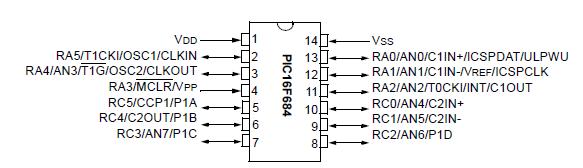
Pinout
 Specifications
| Program Memory Type |
Flash |
| Program Memory (KB) |
3.5 |
| CPU Speed (MIPS) |
5 |
| RAM Bytes |
128 |
| Data EEPROM (bytes) |
256 |
| Capture/Compare/PWM Peripherals |
1 ECCP |
| Timers |
2 x 8-bit, 1 x 16-bit |
| ADC |
8 ch, 10-bit |
| Comparators |
2 |
| Temperature Range (C) |
-40 to 125 |
| Operating Voltage Range (V) |
2 to 5.5 |
| Pin Count |
14 |
Absolute Maximum Ratings(†)
Ambient temperature under bias............................-40° to +125°C
Storage temperature ......................................... -65°C to +150°C
Voltage on VDD with respect to VSS ......................... -0.3V to +6.5V
Voltage onMCLR with respect to Vss ..................... -0.3V to +13.5V
Voltage on all other pins with respect to VSS..-0.3V to (VDD + 0.3V)
Total power dissipation(1) ............................................... 800 mW
Maximum current out of VSS pin ....................................... 300 mA
Maximum current into VDD pin .......................................... 250 mA
Input clamp current, IIK (VI < 0 or VI > VDD)..................± 20 mA
Output clamp current, IOK (Vo < 0 or Vo >VDD)..............± 20 mA
Maximum output current sunk by any I/O pin...................... 25 mA
Maximum output current sourced by any I/O pin ................. 25 mA
Maximum current sunk by PORTA and PORTC (combined) ... 200 mA
Maximum current sourced PORTA and PORTC (combined) ... 200 mA
Note 1: Power dissipation is calculated as follows: PDIS = VDD x {IDD IOH} + {(VDD VOH) x IOH} + (VOl x IOL).
† NOTICE: Stresses above those listed under "Absolute Maximum Ratings" may cause permanent damage to the
device. This is a stress rating only and functional operation of the device at those or any other conditions above those
indicated in the operation listings of this specification is not implied. Exposure to maximum rating conditions for
extended periods may affect device reliability.
Note: Voltage spikes below VSS at the MCLR pin, inducing currents greater than 80 mA, may cause latch-up.
Thus, a series resistor of 50-100 should be used when applying a "low" level to the MCLR pin, rather than
pulling this pin directly to VSS.
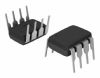
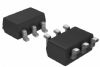
DescriptionThe PIC16F684 is designed as one kind of 14-Pin, Flash-Based 8-Bit CMOS Microcontroller device that is available in 14-pin PDIP, SOIC, TSSOP and 16-pin QFN packages.
Features of the PIC16F684 are:(1)Interrupt Capability; (2)8-Level Deep Hardware Stack; (3)Direct, Indirect and Relative Addressing modes; (4)Power-Saving Sleep mode; (5)Wide Operating Voltage Range (2.0V-5.5V); (6)Industrial and Extended Temperature Range; (7)Power-on Reset (POR); (8)Power-up Timer (PWRT) and Oscillator Start-up Timer (OST); (9)Brown-out Reset (BOR) with Software Control Option; (10)Multiplexed Master Clear with Pull-up/Input Pin; (11)Programmable Code Protection; (12)Program Memory Read/Write during run time; (13)In-Circuit Debugger (on board); (14)High current source/sink for direct LED drive; (15)Interrupt-on-Change pin; (16)Individually programmable weak pull-ups; (17)Ultra Low-Power Wake-up (ULPWU); (18)Timer2: 8-bit Timer/Counter with 8-bit Period Register, Prescaler and Postscaler.etc.
The absolute maximum ratings of the PIC16F684 can be summarized as:(1)Ambient temperature under bias: -40°C to +125°C;(2)Storage temperature: -65°C to +150°C;(3)Voltage on VDD with respect to VSS: -0.3V to +6.5V;(4)Voltage on MCLR with respect to Vss: -0.3V to +13.5V;(5)Total power dissipation: 800 mW;(6)Maximum current out of VSS pin: 95 mA;(7)Maximum current into VDD pin: 95 mA;(8)Input clamp current, IIK: +/-20 mA;(9)Output clamp current, IOK: +/-20 mA;(10)Maximum output current sunk by any I/O pin: 25 mA.etc. If you want to know more information such as the electrical characteristics about the PIC16F684, please download the datasheet in www.seekic.com or www.chinaicmart.com.

 PIC16F684 Data Sheet